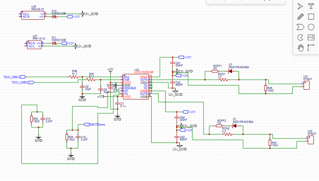
Tool/software:
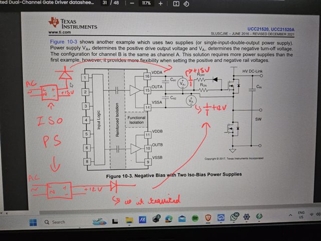
I am using the UCC21520 to drive an IGBT in a half-bridge configuration (SKM100GB12T4 from Semikron). My intention is to apply +15V to turn it on and -12V to turn it off. Based on the datasheet, I believe Figure 10-3 illustrates the appropriate configuration for my application. I have two isolated +15V and +12V supplies on my board.
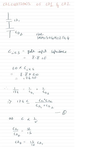
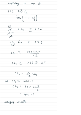
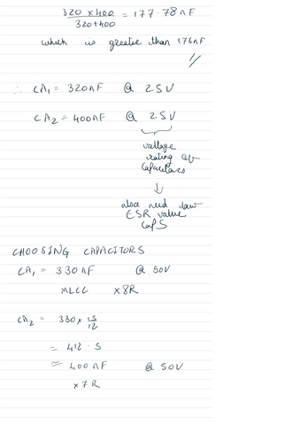
My main concern pertains to the selection of the CA1 and CA2 capacitor values. These values need to be calculated based on the switching frequency (30 kHz) and the gate charge. Could you provide an example of how these values are derived?
Additionally, I have the following queries:
- Should I remove the Rgs resistor that is present in the typical application circuit, or can I retain it?
- Should I add a 1200-V SiC diode to protect my +15V and +12V supplies from high voltage? Notably, when the high-side switch turns on, the high DC bus voltage is directly applied to the -12V supply.
- Can I use the same +15V and +12V supply for both the high and low sides?
Please correct me if there are any misunderstandings in my configuration, as I am still getting acquainted with it. Your guidance on these matters would be greatly appreciated.
