Other Parts Discussed in Thread: UCC27517A
Tool/software:
Dear Rubas,
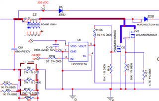
As you know we are using TI gate driver ucc27517A-Q1 ic with our PFC+LLC controller to drive PFC mosfets . PFC out put is 390V - 2.99A.
In previous mail we discuss on some issue regarding UCC27517A failure , and after discussing with you we take action on that like improvising the components.
but now we are facing same problem again , when we conduct reverse diode test on failure gate drive ucc27517A-Q1 ic then we found out pin failed rest pin is ok.
as you suggest in pervious mail on failure ic conduct test VDD pin to OUT pin and OUT pin to VDD pin, then we found
in failure ic when we connect positive probe of multimeter (in diode mode) on VDD pin and negative probe connect to out pin then found 1.121 voltage whereas in the fine IC not showing any voltage. .
and in failure ic when we connect positive probe of multimeter (in diode mode) on out pin and negative probe connect to VDD pin found .600voltage whereas in the fine IC we see .546 voltage.
for reference i have attached the schematic with bom and some wave form at different- different input VAC
 <---- this waveform on trigger mode at 170vac output 54v load 15A , Ch1-out pin current , Ch2-vdd pin , Ch3- PFC mosfet gate (external mos.), Ch4- in+ pin
 <---- this study state waveform at 170vac output 54v load 15A , Ch1-out pin current , Ch2-vdd pin , Ch3- PFC mosfet gate (external mos.), Ch4- in+ pin
 <---- this waveform on trigger mode at 230vac output 54v load 15A , Ch1-out pin current , Ch2-vdd pin , Ch3- PFC mosfet gate (external mos.), Ch4- in+ pin
 <---- this study state waveform at 230vac output 54v load 15A , Ch1-out pin current , Ch2-vdd pin , Ch3- PFC mosfet gate (external mos.), Ch4- in+ pin
 <---- this waveform on trigger mode at 260vac output 54v load 15A , Ch1-out pin current , Ch2-vdd pin , Ch3- PFC mosfet gate (external mos.), Ch4- in+ pin
 <---this study state waveform at 260vac output 54v load 15A , Ch1-out pin current , Ch2-vdd pin , Ch3- PFC mosfet gate (external mos.), Ch4- in+ pin
LLC schematic.pdf0336.PFC schematic.pdfWSJM65R099DX(PFC and LLC mosfet).pdf

Thank
Aditya arya