Tool/software:
Hello!
I am currently experimenting with an SMPS based on the "400- to 690-V AC Input 50-W Flyback Isolated Power Supply Reference Design for Motor Drives."
Contrary to the guide, I am not using a cascade connection at the moment. I am using a single MOSFET as shown in the diagram, and the MOSFET is the same as the one selected in the guide.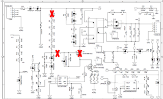
Currently, only the initial 3 PWM pulses are being output, and the system is not operating properly. Therefore, I measured the VS and CS pins.
To minimize risks during measurements, I kept the lead wires short. My experimental setup is as follows:Red circle are lead cable using measurement.
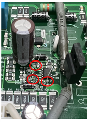
-
For the CS pin voltage: It is in a no-load condition with a shunt resistor of 1.2 ohms. I observed the following waveform. I think this voltage spike is caused by the measurement cable. Therefore, I believe it has not reached the protection voltage. Could you provide any comments on this?
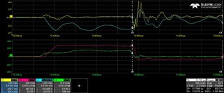 (CH1: Vcs, CH2: VDS, CH3: Vaux, CH4:Vgs//Test input voltage : 500Vdc)
 -
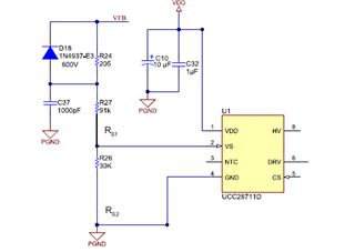
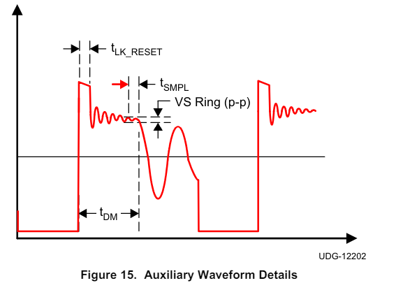
For the VS pin voltage: It is also in a no-load condition, and the waveform is as follows. I think the current voltage on the VS pin is higher than the operating level. So, I am considering reducing the value of R_vs. Could you provide any opinions on this?
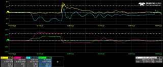 (CH1: Vvs, CH2: VDS, CH3: Vaux, CH4:Vgs//Test input voltage : 500Vdc)
 - And here, what is purpose of D18 diode. And why the Vvs voltage is almost zero when mosfet in on. When mosfet on, Vprimary voltage is almost same with Vin. So Vaux Voltage made by transformer ratio
.