This thread has been locked.

If you have a related question, please click the "Ask a related question" button in the top right corner. The newly created question will be automatically linked to this question.

TPS56C231: TPS56C231: Inquiry about TPS56C231 Specifications

Part Number: TPS56C231
Other Parts Discussed in Thread: TPS56628, TPS566238

Tool/software:

Hi,

We are currently planning to use TPS56C231 for new products.
We have the following unknowns when designing the new product.
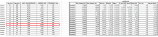
 MODE Selection states to use a 1% resistor. Is it ok to use a 5% resistor if it does not overlap with other modes?

I am trying to use it with internal soft start time.
However, if I add an external cap with a micro capacitance like 10nF for noise suppression, will the internal soft start time be valid?

(From equation 3 in the datasheet, the time calculated with 0.01uF will be less than the internal soft start time)

In another forum (TPS56628), we have received the following answer.

"IC's soft start time is the minimum internal soft start time. If a micro capacitance external cap is attached, the internal soft start time is valid, not the time calculated by the external cap."

Regards, Takumi

  • Hi Takumi,

    1.  For the Mode resistors, it is recommended to use the 1% resistors. I would try to keep within that range to ensure no overlapping in Modes
    2. For the SS time. It is similar to the TPS566238. per the datasheet "The device tracks the lower of the internal soft-start voltage or the external soft-start voltage as the reference". So adding a small enough external capacitor invalidates the equation for SS time and instead refers to the internal soft-start voltage.

    Hope this helps answer your questions.

    Thanks,

    Calan

  • Hi Calan,

    Please let me confirm regarding 1 and 2.
    Please additionally let me know about 3 and 4.

    1: Could you please tell us the threshold voltage of the MODE pin for each mode?
     Currently, in our environment, it is difficult to use 1% products.
     Therefore, we are considering using a 5% resistor for one of the resistors and a 0.5% resistor for the other.

    2: Is it correct to recognize that external Tss and internal Tss have an exclusive relationship?
     We would like to confirm that the soft-start time due to external cap will not be superimposed when internal Tss is used.

    3: Input capacitor
     Is there any problem with the operation of the power supply IC even if the internal capacitor is less than 30uF?
     Our product's input power supply is not used in any other circuit, so there is no problem even if the ripple voltage is large.
     Our product evaluation has confirmed that 20uF (typ) is not a problem.

    4: VREG5
     The datasheet states to use a 4.7uF cap. 
     What is the minimum capacity required?

    Thanks,
    Takumi

  • Hi Takumi,

    1. Sure, I am currently asking a colleague about the details of the MODE pin voltage threshold. I will get back to you on this.
    2. Yes that is correct. To use internal Tss, do not place a capacitor on this pin. To use the external SS time, place the correct capacitor for the desired SS time. Again, placing a small enough cap will invalidate the SS time equation and will refer to the internal SS.
    3. If I am understanding correctly, the question is a concern about input capacitance less than 30uF? TI recommends 40uF on the input capacitance. Anything less is not guaranteed. Please follow this and you can also refer to Equation 9 on input capacitor selection.
    4. VREG5 requires a 4.7uF capacitor. This is a hard requirement and we cannot guarantee a minimum less than this. This pin requires this capacitor.

    I will reply to this post in the next few days regarding #1, the Mode pin voltage threshold.

    Thanks,

    Calan

  • Hi Calan,
    I understand about No.3 and 4.

    1.Is it possible to use a 1% resistor of 1/10 resistance value for the resistor connected to the MODE pin?
    I am aware that the voltage applied to the MODE pin can be 1/10 times the value of each resistor.

    2.What is the lower time limit for the internal soft start time?
    I would like to know what the soft start time would be when I want to connect an external cap of about 10nF for noise suppression.
    If the internal soft start time has a lower limit, I am aware that even if an external cap is connected, the soft start time will not be less than the lower limit.

    Thanks,
    Takumi

  • Hi Takumi,

    1. I received feedback from colleagues about the resistor selection. It was designed to have sufficient margin for 1% external resistor, even 2% might be ok, but so far there is no data that supports 5%. I can check with another person for more details on this. In order to guarantee 5%, test data needs to be checked.

    2. When connecting a 10nF cap on external SS, this will lead to a SS time of about 1ms.

    Thanks!

    Calan

  • Hi Calan,

    As for No. 2, I understood that the SS would operate for about 1 ms, although I don't know whether internal or external SS would apply.

    Can you please continue to check on No.1?
    Currently, I would like to know about the following three things.
    (1) Is there any problem with 5% resistance?
    (2) What is the threshold voltage for each mode?
    (3) Can "10kΩ, 200kΩ" be substituted for "1kΩ, 20kΩ"?

    Thanks,
    Takumi


  • Hi Takumi,

    Yes, I am currently looking into these and will provide feedback end of this week or early next week.

    Thank you,

    Calan

  • Hi Takumi,

    As for the SS time, TPS56C231 has an internal soft-start of 1.2ms and the datasheet also states when there is no external capacitor on SS pin, the internal default SS of 1.2ms applies. The 1ms ss time should be coming from the external capacitor.

    I was able to retrieve data regarding the Mode resistors. I confirmed that 1% resistors have no risk, 1.5% and 2% resistors have little risk, but 5% resistors have a larger possibility risk of the IC entering the wrong Mode. Below is a table that summarizes the Modes and their thresholds. As for substituting resistors, it is best to follow the datasheet resistors when Modes are being selected, this guarantees the correct Mode, otherwise, picking resistors with the same ratio but different resistance values will need to be tested and verified to see if it truly works.

    Hope this helps answer your questions.

    Best,

    Calan

  • Hi Calan,

    I appreciate your help in getting the data.

    There are two things about the table that I do not understand.
    Could you please tell me?

    1. if we want to use mode 4, is it correct that the input voltage to the MODE pin must be 0.2895V~0.3125V?

    2. Isn't the voltage input to the MODE pin obtained by voltage divider with a resistor?
     I was aware that the voltage input to the mode pin when RM_L=10kΩ and RM_H=200kΩ was 0.214V~0.234V by voltage divider with resistors, but this is questionable because it is different from the threshold voltage.
    I am thinking of setting mode 4 with RM_L=1kΩ and RM_H=20kΩ, and would like to know how to find the voltage input to the Mode pin to make sure there is no problem with the input voltage.

    Thank you,
    Takumi

  • Hi Takumi,

    I believe your idea should be correct, but let me confirm this to make sure and I will get back to you.

    Thanks!

    Calan

  • Hi Takumi-san,

    Please allow for a reply by next week as we have TI holiday this week causing delays in reply.

    Thanks,

    Amod

  • Hi Takumi,

    1. The low limit and high limit are ratios in percentage, not voltage limits. VMODE is from MODE pin, which is the center point of the resistor divider. So limit for MODE detection is a percentage of the voltage limit divided by VCC

    2. If the ratio of the resistors is the same and the resistor variation is the same, the resistor swap should be ok, but this combination has not been validated during development. I am attaching some excel calculation files I received from my colleague that might help answer your question.

    Mode Calculation Lakers12A.xlsx

    mode table FT data summary (002).xlsx

    Hope this helps,

    Calan

  • Hi Calan,
    Thank you for your response.
    The attached Excel file has solved my question.

    Thanks!
    Takumi

  • Hi Takumi,

    Happy to help, I will close the thread now.

    Thank you,

    Calan