This thread has been locked.

If you have a related question, please click the "Ask a related question" button in the top right corner. The newly created question will be automatically linked to this question.

BQ25180: I2C not active when operating in Adapter Mode

Part Number: BQ25180

Tool/software:

Hi,

We have noticed that on occasion when VIN is applied without a battery being present, the device (via I2C) is unresponsive.  There is no activity on the TS/MR.  Its like the device is in ship or shutdown mode with no I2C activity.  As the device starts with no power applied (either VIN or VBAT) I can't see how it could get into this state.

When in this state, I can revive the device by applying voltage to the VBAT pin - I then see activity on the TS/MR pin and I2C is active.  I can then remove voltage to the VBAT pin and the device will stay active.

As mentioned this is is 'on occasion' and will sometimes come up working.

Is this something that is known about?

Thanks

Ian

  • Hi,

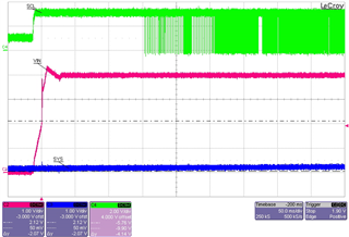
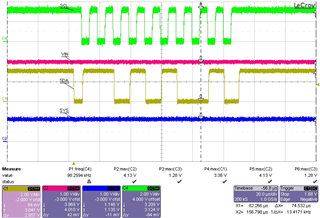
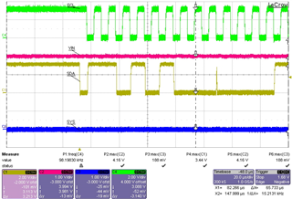
    Can you please confirm SYS voltage, and if possible share waveforms of VIN and SYS at start up in this state and the I2C communication line while trying to communicate with the IC?

    Best Regards,

    Juan Ospina

  • Hi Juan,

    I have attached 3 traces showing 1) the startup, 2) A I2C transmission where the BQ25180 failed to ACK and  3) another where I had manually applied some voltage to the VBAT pin and the BQ25180 ACK successfully.

  • Hi Ian,

    It's unexpected that the SYS voltage should be low with VIN applied, is SYS staying at close to 0 volts the entire time? Is there a large load being applied to SYS? This appears to me as though the device isn't on, which is not expected behavior with VIN being present, although VIN does seem to be fairly low (4V).

    Best Regards,

    Juan Ospina

  • Hi Juan,

    This will be our software doing this. We set 2b11 = SYS disconnected with pulldown.  In our system this charger and battery combination is used as a backup within our platform.

    VIN is at 4V as we use a another single cell battery as VIN.  We only require to keep this backup battery at a mid SoC so we set the termination voltage appropriately

    Best Regards

    Ian.  

  • Hi Ian,

    I'll look into this in lab to see if I can recreate this non-waking state on a lab EVM and if so to determine if the device is even powered on at that point. In the mean time, can you please share your schematic to confirm everything looks good?

    Best Regards,

    Juan Ospina

  • Hi Ian,

    I'm unable to recreate this non-waking state in lab. A 4V VIN should be sufficient to enable the device. What kind of load and capacitance is present on the SYS rail? Also, is there a current limit placed on the input source? Your first waveform seems to indicate that applying 4V doesn't allow SYS to rise at all (i'm assuming BAT is not present here).

    Best Regards,

    Juan Ospina