


Tool/software:
Hi, TI expert
Intermittent defects are occurring in the products equipped with the customer's TPS546D24ARVFR, where a short circuit between the SW pin and PGND pin happens under low current load conditions.
While reviewing the circuit, could you please check if the relevant part of the inquiry below could be the cause of the short circuit problem between the SW pin and PGND pin?
- Problem occurs: Short occurs between SW pin and PGND pin (Singularity: Intermittent short circuit occurs only when the load is small (small load amount < 0.015A))
- PMBUS initial value and 3.3V SET Value: (refer to attached file)
PMBUS initial value and 3.3V SET Value.xls
[Environment when defect occurs]
- FIX Resistor Load: 200 ohm
- Fix Capacitor: 1uF + 10uF + (47uF*8) + 470uF
- Active Load: I2C Driver (TXS0102DCTR) + EEPROM (24FC256T)
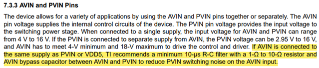
Q1) On the datasheet, “If AVIN is connected to the same supply as PVIN or VDD5, TI recommends a minimum 10-µs R-C filter with a 1-Ω to 10-Ω resistor and AVIN bypass capacitor between AVIN and PVIN to reduce PVIN switching noise on the AVIN input." It says.
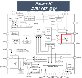
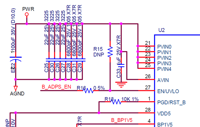
If there is no R-C filter configuration as in the circuit below, will this be the cause of the current problem (short between sw pin and PGND pin)? (U2 is TPS546D24A)

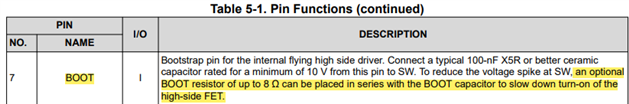
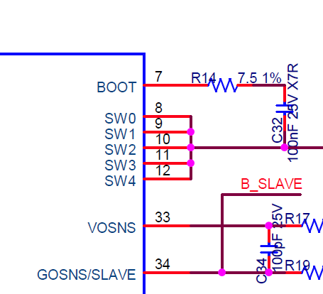
Q2) There is the following phrase regarding "BOOT" in the datasheet.
If the resistance of the Bootstrap value between SW and BOOT is 7.5 ohm as shown in the circuit below, will this be the cause of the current problem (short between sw pin and PGND pin)?
Q3) Additionally, is there a root cause of the short between SW pin and PGND pin? Can you confirm what methods are available to solve the problem?
Please check. Thanks.

