This thread has been locked.

If you have a related question, please click the "Ask a related question" button in the top right corner. The newly created question will be automatically linked to this question.

UCC28951-Q1: No load startup Gate pulse erratic nature observed in CH-C & CH-D

Part Number: UCC28951-Q1
Other Parts Discussed in Thread: UCC28951, UCC28950, UCC28950EVM-442

Tool/software:

Hello Team,

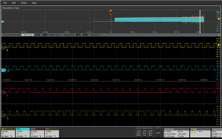
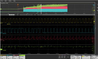
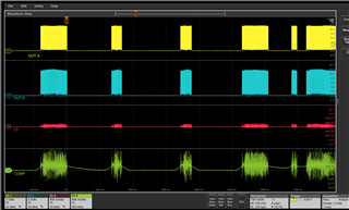
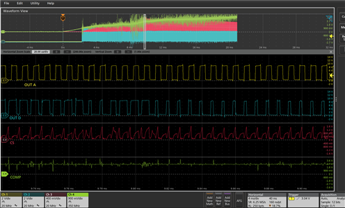
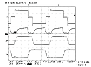
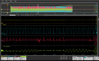
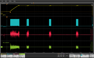
As shown below gate pulses observed in our power converter during startup with no load condition. We operating in peak current mode control, Could you clarify on CH-3 & Ch-4 PWM output nature?

In PSFB , we should get 50% fixed duty at primary side right. Could you help us out?

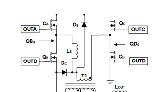
CH1- QA gate , CH2-QB gate , CH3 - QC gate & CH4 - QD gate.

  • Hello,

    The A and B gate driver pulses are synchronized to the master clock with 50% duty cycle.  The C and D gate drive pulses are at 50% duty cycle and are phase shifted to achieve duty cycle.  However, a cycle by cycle current limit can cause the C and D pulse to be phase shifted to demand 0% duty cycle.  This will cause the Out C and Out D pulses to look to be >> 50% and/or << 50% duty cycle.  I believe this is what you are observing.

    You can verify this by studying OUT A, OUT D, CS and comp or OUT B, OUT C, CS and comp.  If the CS signal goes above 2 V the converter will be cycle by cycle current limiting.

    Regards, 

  • Hello Mike,

    It seems CS measurement within limit as attached below images, But lot of variation observed in COMP node.

  • Hello,

    Your inquiry is under evaluation and I will get back to you shortly.

    Regards,

  • Hello,

    Your current sense transformer signal does not look correct.  It should be symmetrical every cycle.  Your signal is trapezoidal then triangular.  This incorrect CS signal is causing the OUT D to be less than 50 % D sporadically.  The UCC28951 is actually OUT D and OUT C to correct the duty cycle based on the CS signal compared to the COMP voltage.

    The following waveform shows the voltage across the input of PSFB transformer (CH1) and the voltage at the CS pin (CH4).  This is what the current sense waveform should look like.  I think you might have an issue with how your current sense transformer is setup. CH2 is the voltage at the gate of QA and CH3 is from the voltage at the gate of of QD.  These waveforms were taken on a 600 W reference design using a 2 to 1 gate driver transformer to drive the FETs on the H Bridge.

    I believe there could be something wrong in how you are sensing your current and/or in your schematic.  The following link will bring you to an application note that goes through the step by step design process of a phase shifted full bridge using the UCC28950 and UCC28951.  You can use this application note to check your schematic and current sense transformer setup.  

    https://www.ti.com/lit/pdf/slua560

    Please note the UCC28950 and UCC28951 are pin to pin compatible.  The only difference is the UCC28951 is design for duty cycle greater than 90%.

    The following link will bring you to an application note that describes the differences between the two devices.

    https://www.ti.com/lit/an/slua853/slua853.pdf

    I do have another recommendation.   It might be useful in the debug process to have a working design to evaluate and compare to your design.

    You might want to order the 600 W phase shifted full bridge evaluation module UCC28950EVM-442.  You can order this evaluation module from ti.com.

    The following link will bring you to the evaluating modules User's Guide which contains critical waveforms, schematic, bill of material (BOM) and layout.

    https://www.ti.com/lit/ug/sluu421a/sluu421a.pdf

    Regards,


  • Hello Mike,

    As per previous thread measurement taken with 100 ohm load. We will just Ignore for a moment.

    Refer following images for no load startup , even though CS signal less than 0.2V , still observing Out D duty variation, Anything are we missing here.

  • Hello,

    I was busy answering our other thread and will look into this thread for you tomorrow.

    Regards,

  • Hello,

    Your current sense transformer signal does not look correct.  It should be symmetrical every cycle.  Your signal is trapezoidal then triangular.  This incorrect CS signal is causing the OUT D to be less than 50 % D sporadically.  The UCC28951 is actually adjusting OUT D and OUT C to correct the duty cycle based on the CS signal compared to the COMP voltage.

    The following waveform shows what the current sense signal should look like (CH4).

    I believe there could be something wrong in the way you are sensing your current and/or with your schematic.  The following link will bring you to an application note that goes through the step by step design process of a phase shifted full bridge using the UCC28950 and UCC28951.  You can use this application note to check your schematic and current sense transformer setup.  

    https://www.ti.com/lit/pdf/slua560

    Please note the UCC28950 and UCC28951 are pin to pin compatible.  The only difference is the UCC28951 is design for duty cycle greater than 90%.

    The following link will bring you to an application note that describes the differences between the two devices.

    https://www.ti.com/lit/an/slua853/slua853.pdf

    I do have another recommendation.   It might be useful in the debug process to have a working design to evaluate and compare to your design.  The differences in performance, layout and schematic could help you figure out why your design is not behaving as expected. 

    We do have a 600 W evaluation module using the UCC28950, UCC28950EVM-442 that is a working design that you could use to compare to your design as mentioned above.  You can order this evaluation module from ti.com.  The following link will bring you to the evaluating modules User's Guide which contains critical waveforms, schematic, bill of material (BOM) and layout.

    https://www.ti.com/lit/ug/sluu421a/sluu421a.pdf

    Regards,

  • Hello Mike,

    As you mentioned CS signal affected because of CT secondary reset resistor kept around 100Kohm. After modifying that with recommended value,100 times of Rsense.

  • Hello,

    Are you still having issues with this?

    Regards,

  • Hello Mike,

    We are working on two different power conversion application,

    Application 1: 80 to 120 Vin , 14Vout , 450W, PoL application ,CV regulation 

    Application 2: 400 Vin , 80 to 120 Vout , 2400W , Battery charger, CC/CV regulation

    As per previous thread OUT C, OUTD duty issue solved in Application1.

    But still observing in another Application 2 circuit, Thatsy new thread created as per below link,

    https://e2e.ti.com/support/tools/simulation-hardware-system-design-tools-group/sim-hw-system-design/f/simulation-hardware-system-design-tools-forum/1391012/pmp8740-out-c-out-d-duty-going-above-below-50-approx-80-or-20-sometimes

    All required SCH, Layout information already shared with local TI FAE team, hopefully you might have received the same.

    Could you suggest any other possible causes of << or >> 50% duty in out C & D, Like PCM slope compensation ?

    Thanks & Regards,

    Babu S


  • Hello,

    So this thread in regards to application 1 has been resolved.

    Your second issue below has been assigned to power supply design engineer who designed PMP8710.  Please have your local AFE share the schematics with the power supply design engineer who it looking into this issue for you.

    https://e2e.ti.com/support/tools/simulation-hardware-system-design-tools-group/sim-hw-system-design/f/simulation-hardware-system-design-tools-forum/1391012/pmp8740-out-c-out-d-duty-going-above-below-50-approx-80-or-20-sometimes

    Since this is a new issue with a different design I will close this post and let the power supply design engineer help you with the PMP8710 issue.

    You might want to have the local TI FAE you are working with share the schematics with the power supply designer?

    Thank you for interest in Texas Instruments (TI) products.  If you have a related question, please click the "Ask a related question" button in the top right corner. The newly created question will be automatically linked to this question.

    Regards,