LM5158-Q1: Boost Converter

Part Number: LM5158-Q1
Other Parts Discussed in Thread: LM5158, AMC1200

Tool/software:

Hi TI Team,

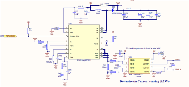
I am planning to use the LM5158-Q1 for a POE application to boost the voltage from 40-50Vin to 52Vout/1A. I have the following queries:

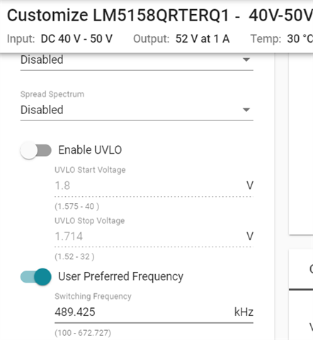
  • The datasheet specifies that the device supports up to 2.2MHz. However, in Webench, it shows a maximum frequency of 672kHz. Could you please explain the discrepancy?
  • The maximum start voltage for UVLO is specified as 40V in the webbench, but Vin max of the device is 65V. I would like to set the minimum start voltage to 42V. 
  • How does the boost converter behave when the input voltage is higher than the set output voltage (52V)? For instance, if Vin is 54V, will the boost converter pass through the 54V as it is, and what are the implications of this scenario
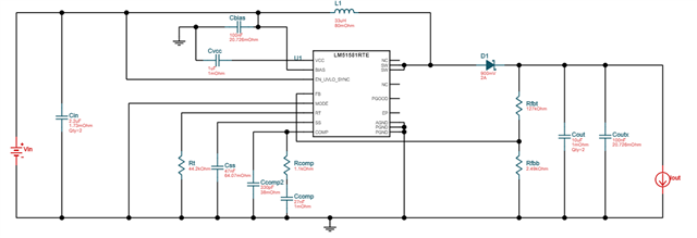
  • please review the below snip of schematic from webbench and confirm.

  • Hi Reddy,

    Thanks for uusing E2E.

    Thats right, LM5158 allows up to 2.2MHz. Depending on for what you optimize the design, webench will choose the switching frequency for a good efficiency and it also optimizes for CCM.

    UVLO can be set to 42V. Please use the formulas given in the datasheet or use the quickstart calculator.

    For the case that Vin is higher than Vout, the device will stop switching und just pass through. So at the output you will have Vin minus diode drop.

    In general i recommend to use our quickstart calculator for your design: https://www.ti.com/tool/download/SNVR511
    Also the powerstage designer is a very good tool to check the design and adjust compensation loop: https://www.ti.com/tool/POWERSTAGE-DESIGNER#downloads

    Best regards

    Moritz

  • at Input of 52V I have a boost converter that is making a hissing noise from the inductor and not supporting more than 100mA. The boost IC also heats up (~80degC). I tried using a 47k resistor (~450kHz frequency) but encountered the same problem. I also tried different output capacitors, using four 10uFx4 nos capacitors in place of the 22uF aluminum cap, but the issue persists. Inductor MPN IHLP6767GZER680M11

    Can you please help me identify the cause?

    To bypass the boost is that OK if i place 0R (R151) in between VIN (44V-54V) to VOUT ? Do you see any issue ? How does boost IC behave if i do so ?

  • Hi Reddy,

    does your boost work in normal operation when the input voltage is smaller than the output?

    Can you please send some scopeshots? Iw ould like to see Vin, Vout, switchnode and FB.

    Best regards

    Moritz

  • Hi Moritz,

    Can you please help me review the shared schematics to identify any issues that might be causing the audible noise in the design? Meanwhile, I will capture the requested waveforms.

    The circuit is designed to work with an input voltage range of 12V-50V and boost it to 52V. It's functioning correctly with input voltages greater than 20V, but when a load of 0.2A is added, there's audible noise coming from the inductor. We are OK if its working from Vin 40V-50V to boost to 52Vout. 

    Thank you for your assistance.

  • Hi Reddy,

    The waveforms will help me identifying the issue.

    The internal switch has a current limit of 3.26A min. So with Vin less than 18V and Vout=1A you might trigger the current limit already.

    Best regards

    Moritz

  • Hi Moritz,
    As i mentioned issue of Inductor audible noise observed at all Volatges from 20V-48V, with output 52V/<0.2A also.

  • Hi Reddy,

    The compensation might be a root cause for this.

    Please try to adjust the values (after taking the scopeshots) to Rcomp=8k, Ccomp=10nF, Chf=22pF

    Best regards

    Moritz

  • Attached scope shots for your review and suggestion

    Able to reduce the audible sound to reasonably low by tuning Ccomp, Rcomp & Input and Output caps.

    Need your support in eliminating. 

    4010.LM5158 Audible Sound Issue scope shots.docx

  • Hi Reddy,

    Thanks for the scopeshots.

    It seems that your boost converter is not really regulating. Please first disconnect the AMC1200 from the ground path. Connect AGND and PGND directly and short to ground. Then please send scopeshots and an updated schematic with the updated values again.

    I am looking forward four your response.

    Best regards

    Moritz

  • 7215.LM5158 Audible Sound Issue scope shots.docx

    attached as per your request. i am running out of time, our PCB assembly is on hold.
    Can you kindly support on this ASAP. 

    we can have a teams call if required. 

  • Hi Reddy,

    now your converter seems to be in regulation at least.

    The noise can also come from MLCC capacitors. Please have a look at this appnote:

    https://www.ti.com/document-viewer/lit/html/SSZTB09

    You can try to exchange the ouput capacitors. Also please try to increase input capacitance.

    Best regards

    Moritz

  • Yes, the sound is coming from the MLCC. When I touch the output MLCCs, the intensity of the sound reduces. As you suggested, I removed all output MLCC caps and used aluminum 22uF/100V caps instead. However, the audible sound is still present. When I touch the input capacitor with a probe, the sound intensity changes, which implies that it's now coming from the input caps. Am I correct? Despite several attempts, we are not reaching a solution. Are we missing something?

  • Hi Reddy,

    I would recommend to keep some ceramic caps and dont change all to aluminum. They are needed for the higher frequencies.

    You can use special types like shown in the appnote:

    Regarding the input capacitors, please try to increase the total input capacitance.

    Use one or two of the aluminum caps for the input additionally.

    Best regards

    Moritz