This thread has been locked.

If you have a related question, please click the "Ask a related question" button in the top right corner. The newly created question will be automatically linked to this question.

LM5145-Q1: LM5145-Q1-Load regulation

Part Number: LM5145-Q1
Other Parts Discussed in Thread: LM5145, LM5146

Tool/software:

Hi !

This is Venu Gopal.

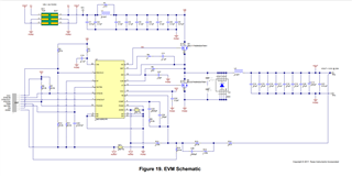
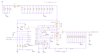
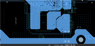
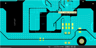
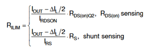
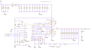
I have designed a DC-DC converter by using LM5145-Q1 buck switching regulator IC. I have designed it for an output of 24V and 20A output current. I have set a current limit of 30A by using the ILIM pin of LM5145 by connecting a resistor with value of 1.69Kohm. Now while I am performing my load tests output voltage is not regulating by LM5145 IC. Voltage is dropping to 14V, 16V and 18V when I am trying to draw current of more than 7A. What are the reasons for this voltage drop and what are the modification I need to do to my circuit? I am attaching Schematics below for the reference.

Thanks in Advance

  • Hi Venu,

    Send on a completed quickstart calcualtor file (this is a critical file in circuit design, particularly to understand bode plot, power losses, etc.) https://www.ti.com/tool/LM5145DESIGN-CALC. Also, let's review the PCB layout -- see app note SNVA803 for component placement guildance.

    Also, see apps circuit #3 in the LM5145 datasheet for reference (24Vout, 150W, 440kHz).

    Regards,

    Tim

  • Are the snubber caps really 0.1uF here? Try 220pF as a starting point (or leave it unpopulated)

  • Hi Timothy,

    I have tried with replacing the capacitor with 220pf as well as opening that capacitor both, still the voltage is dropping to 19V from 24V, when I am trying to draw more than 6A current. I have checked with replacing the current limiting resistor from 1.69Kohm to 422 Ohm resistor as per EVM circuit and checked still the voltage is dropping to 16V from 24V. kindly provide the best possible solution to avoid the voltage drop.

    I have attached EVM Schematics and my design Schematics for your reference.

    Thanks in Advance.

  • Go ahead and fill out the quickstart calculator file available here https://www.ti.com/tool/LM5145DESIGN-CALC. The current limit setpoint depends on the MOSFET Rdson. It should have increased by 4x when you reduced from 1.69kΩ to 422Ω.

    What is the input voltage here? You may not need 100V FETs -- 60V or 80V may be sufficient. The SIR870DP has high Qrr, 82nC, which may be increasing the overall noise level and affecting the controller operation.

    Send on the PCB layout for review.

  • Could you please explain how it will be related or depends on the MOSFET Rds(on) because equation not given in the design calculation excel. Kindly provide the equation for calculating current limiting resistor value with Rds(on). 

    It should have increased by 4x when you reduced from 1.69kΩ to 422Ω. - could you explain this line some more detailed way?

    Input Voltage = 60V, for derating purpose I have selected MOSFET with 100V Vds. I have used another MOSFET with part number DMNH10H028SCT with Qrr 46.8nc its capable of 15A - 25A continuous current but this is TO-220 Package MOSFET. will the MOSFET package will have any impact on load current (Output power)? SIR870DP is a SMD MOSFET. could you please elaborate more detailed about this qrr value of MOSFET impact on load current.

    Further I am attaching my layout images below. Copper thick ness is 1ounce.

    Top layer

    second layer

    Third layer

    Bottom layer

  • See equation 6 as provided in the datasheet as follows:

    In terms of layout - follow the guidance in the datasheet and refer to the LM5145 and LM5146 EVM layouts in particular.

    For example:

    1. Layer 2 under the power stage components should be a solid GND plane.
    2. Avoid SW vias or internal SW copper.
    3. Route the HO and SW traces together from the controller to the high-side FET.

  • The power loss equations are given in the MOSFET section of the datasheet. I recommend avoiding TO-220 package FETs - too much inductive parasitics.. SON 5 x 6mm type devices will give much better performance. See the LM5145 and LM5146 EVMs for reference and also the circuit examples in the datasheets.

  • Thank you, Tim

    I will do the modification as you suggested and let you know if I have further queries in the same thread of load regulation.

  • Thank you, Venu.