This thread has been locked.

If you have a related question, please click the "Ask a related question" button in the top right corner. The newly created question will be automatically linked to this question.

BQ77915: BQ7791508 turning on and off

Part Number: BQ77915

Tool/software:

this is a new thread in continuation of this one: (+) BQ77915: Charging only up to 4,0V, No Balancing observable - Power management forum - Power management - TI E2E support forums
since the old problem is resolved so i clicked "solved". But now there is a new issue.

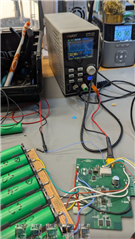
I just tried again with a second board using bq7791508 and unbalanced batteries. 3 Batteries in the stack have 3,9V, four have 4,0V. started charging, observing this behaviour:
supply

The CHG FET is turned off after a few seconds and then on again after a few seconds.
is this normal, expectable behaviour?

the OFF-durations are getting longer each time.

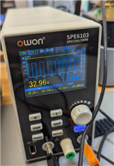
while the charger is on, the "4,0V" cells are at ~4,15V


... i think maybe the 50mA internal cell balancing are not enough, when using a 3A charger.

  • Hello,

    A few questions:

    1. Can you look at the TS pin and make sure it is within a reasonable value?

    2. Can you check to make sure there is no noise on the CTRC pin?

    3. Can you check the sense resistor to make sure a current based protection is not triggering?

    4. Is this happening to DSG as well?

    Best regards,

    Thomas Rainey

  • Hi there, sorry for late reply. I just wanted to check on these things, but a new problem came up:

    I discharged the battery pack, and now some cells are at  ~3.2V some at ~3.4V (of that unbalanced pack from before).

    I guess the BQ went into UV mode, while it was still discharging the voltage might have reached that point. Now that DSG and CHG FET are closed, maybe they have recovered some voltage. 

    But CHG and DSG FET stay closed. When do they open again? How can I charge the pack now?

    edit: after a long time ( >1h ) they were open. do they add up when load removal isn't detected after delay expired? just like in the OV situation when the OFF-durations are getting longer each time.
    Datasheet says something like "The CTRx deglitch time will add onto the FET response timing on the OV, UV, and OW faults in a stack configuration. The tCTRDEG_OFF time adds an additional delay to the fault detection timing and the tCTRDEG_ON time adds an additional delay to the fault recovery timing."

  • maybe i have found the issue. my Rctrx Resistors ar not closer to the lower device in my layout.

    but one more thing: shouldn't the ground plane from the upper device be extended down under those traces like my yellow marking to shield them/ to not have a split in their reference plane? Datasheet says "Although such a filter scheme provides a certain level of noise tolerance, it is highly recommended to shield the CTRx traces and keep the traces as short as possible in the PCB layout design. "

  • Hello Marv,

    The short answer is yes.

    Although a deglitch and other filtering is provided it always recommend to use PCB layout design guidelines. Such as, keep traces as short as possible, providing shielding for traces, having adequate ground connections. 

    Best regards,

    Thomas Rainey

  • Hello Thomas,

    new PCBs have arrived with improved layout. It seems to work a bit better now, when testing with unbalanced Batteries. I am charging a pack right now. 
    most of the time it is charging fine in CC mode with 1.8A. But then for a few Minutes it shows on/off/on/off behaviour again. But at least it was now charging until  Some cells are at 4.1V, some at 4.0V. but then it doesnt stop to go on/off/on/off. But then if I limit the charging current to 1A its working fine again. 

    also it seems like measuring cells with multimeter also triggers the problem.

    CTRC doesnt seem noisy, but measuring alone seems to impact the situation as well. (right now CHG is closed, but as soon as i measure CTRC pin CHG is opened) TS is fine, since i am using a 10k resistor for testing (not a NTC). Sense Resistor is 10mOhms, so it should turn off at 6A, and that works fine, I tested it. Only the chg-FET turns off. 


    1321.Balancer_7s3p_v2.pdf

    it seems to me  that the BQ is a balancing chip, that doesnt like, if cells are too unbalanced

  • Hello Marv,

    Can you send the up-to-date schematic?

    As for cell balancing I recommend watching this video: https://www.youtube.com/watch?v=wewL0oJRBNM It works a little different.

    Best regards,

    Thomas Rainey

  • thank you for your answer.

    so you are saying what I am seeing is the balancing in OV mode? but why does it already happenat 4V with BQ7791508?

    and why is my circuit so sensitive to my measuerements with multimeter or osci?

    are 33Ohms maybe to low? that would be already 125mA at 4.2V, no?

    i dont really understand the example calculation: " Determine the resistance for the RIN filter resistors. Since the charge taper current will be 0.05 × 5 A

    or 250 mA, 10% is 25 mA. With a 4.1-V cell, 25 mA would require 164-Ω resistance. This resistance

    includes the internal RBAL resistance and two RIN resistors. 75-Ω resistors are selected for RIN."

    which internal RBAL? why two RIN?

  • [deleted]
  • thank you for your answer.

    so you are saying what I am seeing is the balancing in OV mode? but why does it already happen at 4V with BQ7791508? but i think you are right. I can observe balancing with my osci, even though its not charging. so it must be that. thank you for the video. clears up a lot

    But why seemed my circuit so sensitive to  my measurements with mulltimeter? are 33Ohms maybe to low? that would be already 125mA at 4.2V, or not?

    i dont really understand the example calculation: " Determine the resistance for the RIN filter resistors. Since the charge taper current will be 0.05 × 5 A

    or 250 mA, 10% is 25 mA. With a 4.1-V cell, 25 mA would require 164-Ω resistance. This resistance

    includes the internal RBAL resistance and two RIN resistors. 75-Ω resistors are selected for RIN." (why two?)

    RBAL is between 8 and 20ohm, normally 12ohm. so 33+12=45Ohm  4,2V/45ohm=93mA..still more than 50mA

    Balancer_7s3p_v2_sch.pdf

  • Hello Marv,

    The current path of the cell balancing current goes through three resistances, so the current would be 4.2-V / (33-Ohm + 12-Ohm + 33-Ohm) = ~53.85-mA.

    Best Regards,

    Luis Hernandez Salomon