Tool/software:
Hi Expert,
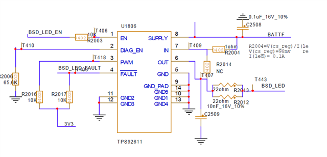
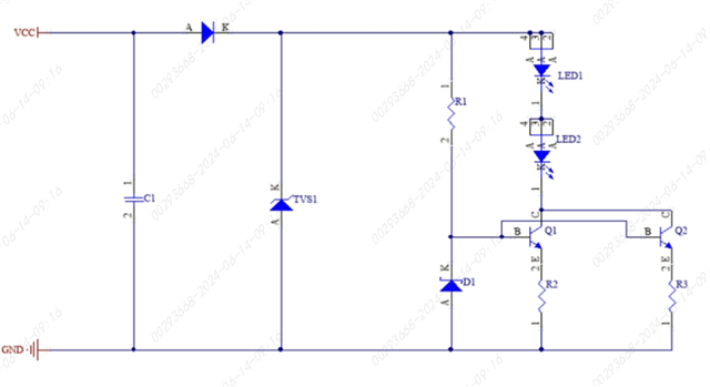
Would you please help to have a review on the schematic? Is there any mstake? We have 4pcs PCBA broken, and finally found all of them are TPS92611-Q1 broken, pin5 short to pin6 when it is unistanlled on PCBA.
Tool/software:
Hi Expert,
Would you please help to have a review on the schematic? Is there any mstake? We have 4pcs PCBA broken, and finally found all of them are TPS92611-Q1 broken, pin5 short to pin6 when it is unistanlled on PCBA.