This thread has been locked.

If you have a related question, please click the "Ask a related question" button in the top right corner. The newly created question will be automatically linked to this question.

TPS2493: TPS2493PWR

Part Number: TPS2493

Tool/software:

hi,

i also have a problem with my TPS2493PWR its stange behaviour at least thats what i think of it but i am still learning bits so i am curious to your findings.

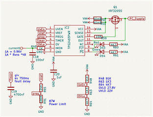
i have a tps2493 i was testing the features to see if the circuit is good.

all was great until the output short circuit test.

at around 20-21V the current limit state is constantley on. e.g. i am burning 21V0.6A (12W) trough my fet. its heating up way too fast.

i ahve a 1uF cap on timer why does the output not switchoff at 160ms?

the stange thing is above the 21V it works fine...

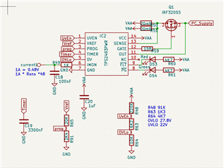
can you look at my schematic and see if i made a miscalculation somewhere?

is the behaviour at 20-21V normal? what could i do to make shure the fet is not burning up as fast?

looking forward to your findings,

BR.

michel datema

  • Hello Michel,

    You have set UVLO at 22V as mentioned in schematics.

    For the FET to operate in saturation mode, VIN must be higher than UVLO set.

    Thanks 

    Amrit 

  • Hi, 

    I dont really understand what you mean by that.

    Uvlo is 22 at vin of the resistor devider. At the uvlo pin is 1,25 (or so) volt.

    E.g. the vin is always higher as uvlo.

    Is this what you ment?

    The fet works from 2-10v at the gate. Absolute maximum voltage is at 20v according to the datasheet.

    I have a theory please help me think: what is the short circuit draws so kutch current that the voltage on the input drops under uvlo level. That the ic switches off. Voltage rises and over again. I am going to check these levels with the scope. Ill update later.

  • Nope nonresoult.

    The uvlo pin switches off at exactley 1,25v and on again at 1,31v.

    When the output is osculating at about 2khz the voltage does not go below 1,25v

    The output oscilates at about 2khz it is a noticable sound from the fet. The led that is connected to the FLT pin is dim. I suppose that its oscilating as well the PG led is off.

    Is there any data i can provide more/better?

  • is the behaviour at 20-21V normal?

    which node voltage you are asking over here?

    Is it the VAA voltage as per the schematic nomenclature?

  • Yes. When vaa is under 22v (orso) the uvlo pin goes below 1,25v and the output is switched off. Pg and flt led are off. 

    The oscilation i have is from 1,25v to about 1,33v or so... (At uvlo pin) 

    In my application the power supply is a battery that can be drained. So the chanse of vaa going from 23 to 22v is very likeley to happin. E.g. i will cirtainley burn the fet now.

  • hello,

    i did some more tests and reopined the calculator tool of the IC

    i uploaded the file maye you can detect the problem.

    i have tested. now:

    with load (led lamp)

    VAA (Vin) transitionning from UVLO off to above UVLO ON this case 22V to 23.5V

    as soon as the voltage rises above 22V the fet is switched on with a crude wave not a clean squarewave but

    frequency at gate is variing from 1.3 to 17Khz. it is a noticable sound.

    voltage at timer remains 0volt

    --> but voltgage at PROG rises from 0 to 0.4V <-- is this normal? if uvlo switches on than this seems normal.

    after the voltage rises about 23.2V the ERR led switches on and the voltage at prog becomes 0 again.

    when i remove the load there is no problem the PG led switches on an all is good.

    if i use a small inductive load (small motor) than the motor starts turning

    if i use a too small resistor in this case 3.9Ohm than i have the problem after 23.5V the FLT led switches on. retrys some over and over (normal)

    if i use a very large capacitor 47000Uf paralel to the motor the high frequency noise is present for <1s and than the motor switches on

    it appears when the current is higher than the 2.5A current limit than this high frequency noise is present when the UVLO switches back ON.

    please curious to your findings

    2642.TPS249x_8x_Design_Calculator_REV_B.xlsx

  • Hello Michel,

    Any particular reason why you are operating the FET slightly below UVLO ON?

    Can I know the application for which you are using the Hot swap controller?

    What exact support you are looking for from us about this device?

    Thanks

    Amrit 

  • hello,

    what do you mean by runnung the fet under uvlo on?

    did you mean why i am lowering vaa to the treshold of uvlo?

    that is becouse a battery that is beeing discharged can also be at these voltage levels.

    the application:

    a trailer with gel/agm batterys, solar battery chargers and a ;arge charger. at the input. (24V // 440Ah)

    also 2000W electric PM motor onboard so i fear also for voltage peaks

    the hotswapcontroller protects a industrial pc with a large pricetag. so we never supply over or under the specs of this PC.

    long cables trough a chassis and so on.

    i want to protect against:

    overvoltage, undervoltage

    voltage spikes / transients

    overcurrent

    wire break and short circuit

  • One more thing:

    I just tested out the putput response with re resistor in series with the load.

    This works without problems. It was a 3.9Ohm resistor. Wit a 2amp load the led lamp in this instance. (Also testend with 2pcs)

    I tested a 47uH inductor at the output but that didnt make a difference.

    Also bypassed the psd760 shottky diode at the input but the resoults didnt change

    Just sharing im not shure what to think of this. Maybe the powersupply track to the ic is too small or something but i cant get any readings on this on the scope of there is a difference that the difference is too small to mesure

  • Hey Michel,

    Sorry for the delay in reponse

    I am still not clear about the exact test case and failure.

    You are basically doing short circuit test on 21V,0.6A and found that the FET is having high temperature.

    Please let me know the exact test condition which you are doing.

    Will try to replicate if possible.

    Do you have any waveforms? That could help to analyze.

  • i am doing following tests:

    Nominal load, overload, open load and short circuit.

    and on tests where there is a load ivolved the problem occurs at around 21V the turn on voltage from UVLO.

    i dont think you need to replicate but i do need some help.

    since my last tests i changed the resistors connected to PROG. (first with a potentiometer later with fixed resistors)

    this way i was able to work out at what position the problem starts.

    i have no real value i believe it was about 1/4th of the range of the pot.

    now the system works without problems. good startup. swithces of at overload retrys and so on.

    only one problem that concerns me.

    if i change the resistor values in the excel calculator sheet. than i get some red boxes. telling me that i am now at 20% of SOA (SafeOperatingArea) of the FET. i cant get my head around that why. in my head this fet and drive should easily be aplicable for this system

    can you have a look at that? and explain to me what the reason is and even better what i can do to change it.

    i have watched the videos but couldnt really understand where this problem comes from.

    thanks in advance.5582.TPS249x_8x_Design_Calculator_REV_B.xlsx

  • Hello Michel,

    Based on the input values given in design calculator two boxes are coming red 

    1.IFET - ILOAD margin (lowest for Vout range) : It's coming red because you have put starting load as 9 ohms which means ILOAD=2.67 A but you have given max current as 2.25A on step-1. Please increase the starting load value at F70.

    2.Derated SOA / PLIM: This is coming red because you have put 1A in 1s or DC SOA Current at @ VIN(MAX) (use DC if 1s not available) and also for 100 msec. Which looks to be wrong. Please use correct value from MOSFET datasheet.

    Thanks 

    Amrit  

  • hi,

    i changed some values my on resistance is normally about 1Kohm or so i dont understand why i put this not so smart the system wors form 15 Ohm thats good:)

    but i dont understand what you mean. the SOA table i could find but i cant find anything with DC on the table.

    i think i am missing one rediculousley simple detail could you explain to me what the DC value is?

    thanks in advanse

    michel

  • Hello MIchel,

    Please check F58,F59 cell in design calculator.

    Please add the correct the value from datasheet. These were the reason why your Derated SOA / PLIM (F78) was coming red.

    Thanks

    Amrit