This thread has been locked.

If you have a related question, please click the "Ask a related question" button in the top right corner. The newly created question will be automatically linked to this question.

TPSM63606: Short between VIN, VOUT and PGND

Part Number: TPSM63606

Tool/software:

Hello,

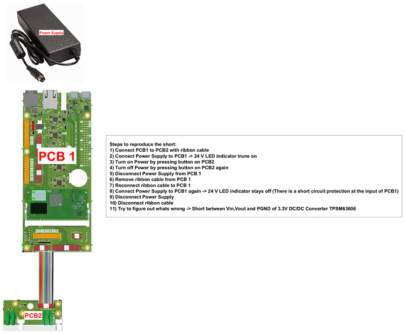
I have two boards connect together via a 10 cm ribbon cable. The voltage (+3V3) from a TPSM63606 is running through this cable. I killed 3 TPSM63606 on three different boards when doing the following:

1) Switch off main power ( EN+3V3 goes low).

2) remove Main Power Connector (24V) at P1.

2) disconnect ribbon cable from J5

3) reconnect ribbon cable to J5

4) plug Main Power Connector back into P1.

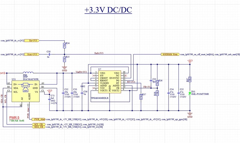
At this point I have a short between Vin, Vout and PGND of U7. This happend on three different boards. What would case the FETs of the output stage of TPSM63606 go short?

Find relevant schematics below:

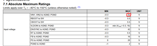
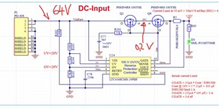
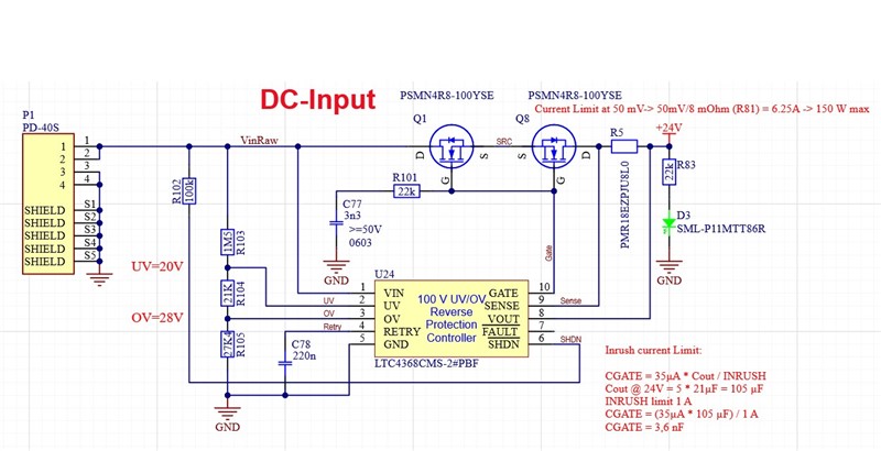
Vin (24V with Protection Controller)

TPSM63606 (24V in , 3.3V out) :

Connection to other board:

  • Hi Jan,

    I believe we need more information. Maybe you can send me schematics of the relevant PCB's. Also, for clarity can you draw a diagram of how each thing is connected at each step?

    Thanks,
    Andrew

  • Hi Andrew,

    thanks for your quicj reply.

    Here are the requested schematcis:

    Schaltplan_lp00799-01.PDF

    lp00803_outjob.PDF

    And here is a descciption of how to reproduce the short:

    Please let me know if you need further information.

    Best Regards

    Jan

  • PCB1 is lp00799

    PCB2 is lp00803 but not all of it. This PCB is cut into to part. Only the part with the buttons and leds are relevant.

  • Hi Jan,

    Do you think there's anything downstream of TPSM63606 that's giving you grief? Is this the only part that's giving you trouble. Do those steps reproduce the broken part 100% of the time?

    Thanks,

    Andrew

  • Hi Andrew,

    there is nothing else connected to the TPSM63606 than the parts on PCB1. There is a CPU Module in the SODIMM socket but that all works fine as long as I do not unplug and replug the cable.

    I do not know when exactly the TPSM63606 goes short. It may be when I unplug the ribbon cable or when I reconnect it.

    I have had this issue with three out of five boards so far. I do not dare to test it on the last two boards because I need them for product development. As long as all is connected together it all works fine. I did a load test on the TPSM63606 and they deliver 6A with no problem. I only have trouble when I have to change the setup and unplug replug the ribbon cable.

    Well, my initial question was what event would make the Fets in the outputstage of the TPSM63606 go short?

    Any idea about that? What do I have to look for if I repeat the test with plugging and unplugging? What pins should I monitor?

  • Hi Jan,

    Is there an over voltage event happening? That's definitely something that can blow out the FETS. I don't see any Voltage clamping mechanism (like a zener diode) at the input of the TPSM63606 or at PCB1 after the power supply is connected.

    Thanks,
    Andrew

  • Dear Andrew,

    Under- and overvoltage protection is implemented by U24 (LTC4368) .

    U24 does not open FETs Q1 and Q8 if ViinRaw is below 20V or above 28V and so the TPSM63606 do not see more than 28V.

    I tested this by applying up to 64V to P1 (on a board where we removed the shorted TPSM63606) with a bench power supply and measured the voltage at Q1 Pin D and Q1 Pin S.

    While 64V is at Pin D there are only about 0,2 V at Pin S.

    When I turn the bench supply below 26.5 V  Q1 opens and the (remaing 4) TPSM63606 are still alive.

    So I think it Overvoltage Protection works or do you think I need to add Zener diodes?

    I also measured the voltage at C32 (VinFlt+3V3) with a 500 MHz scope and I do not see any voltage more then 24 Volt if I plug powersupply at P1 or ribbon cable at J5.


  • Hi Jan,

    Can you share your layout for the TPSM63606 area?

    Thanks,

    Andrew

  • Dear Andrew,

    attached you find the gerber files for PCB1.

    lp00799.zip

    Best Regards

    Jan

  • Hi Andrew,

    do you have any suggestions what do to make the design saver?

    Best Regards

    Jan

  • Hi Jan,

    I'm just thinking out loud here. Is there any power on PCB 2 when it's connected back to PCB1? I'm just wondering if the VLDO_in pin is causing our device to be damaged.

    Do you have any spare TPSM63606's to rework onto broken boards on to test anything. I'd like to see VIN/VOUT/SW/VCC voltages when the device pops and during your procedure.

    By the way I checked the layout. It seems fine, although there are some 0 ohm/1 ohm resistors on the EVM that make it easy to disconnect various pins from other pins that would be nice if they existed. Mainly one for VLDO_in and CBOOT.

    Thanks,

    Andrew

  • Dear Andrew,

    after breaking down the problem into pieces I ended up with the following:

    1. The Problem has nothing to do with PCB 2. 

    2. There are two different scenarios that kill the TPSM63606.

    2a. There is a negative voltage transient when unplugging the 24V Power in supply voltage. This goes down to minus 10 Volts and will most likely have killed some of the TPSM63606. The solution is to add a transient surge filter like it is shown on the TPSM63606 evaluation board.

    2b. There is a design problem in the USB Part which can lead to a short between 5V supplied from TPSM63606 and 5V from USB connector which seems to kill the TPSM63606. A simple diode fixes this problem.

    I have been running and plugging the modified board for a few days on and it looks like the fixes work.