This thread has been locked.

If you have a related question, please click the "Ask a related question" button in the top right corner. The newly created question will be automatically linked to this question.

LM5116: How to limit the output current

Part Number: LM5116

Tool/software:

Dear All,

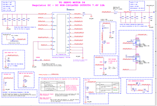
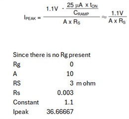
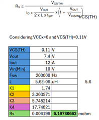
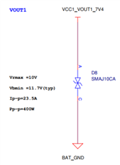
We are using an LM5116 DC-DC converter in one of our projects. The specifications areas follows. Vin - 10 - 55V. Iout=12A and Vout=7.4V. we are using 4 dc-dc converters in the design. We tested initially with load and everything is working fine. We took the design to EMI/EMC by connecting the outputs to servo motors. After the EMI/EMC Test, the two channels are not giving the output. Could you please explain how the current limit works and how it can be limited? We did the design using webench and used the same circuitry.

Thanks & Regards,

Ashok

  • Hello Ashok 

    Please check which pin is damaged. Especially, please check the VOUT pin. The motor load sometimes causes a negative voltage surge at the VOUT pin and damage the  device during shutdown. 

    Current limiting function is described in detail in the section 6.3.7 of the datasheet. https://www.ti.com/lit/ds/symlink/lm5116.pdf 

    The LM5116 contains a current limit monitoring scheme to protect the circuit from possible over-current conditions. When set correctly, the emulated current sense signal is proportional to the buck switch current with a scale factor determined by the current limit sense resistor. The emulated ramp signal is applied to the current limit comparator. If the emulated ramp signal exceeds 1.6 V, the current cycle is terminated

    -EL  

  • Hi Lee,

    Thanks for the reply.

    When I do the calculation, in the datasheet, they have given two formulas.

    'If the emulated ramp signal exceeds 1.6 V, the current cycle is terminated (cycle-bycycle current limiting). Because the ramp amplitude is proportional to VIN - VOUT, if VOUT is shorted, there is an immediate reduction in duty cycle.' - How long does it take to switch off the converter?

    When I calculate the Ipeak asper the webench design with 7.4V/12A current the RS=3mOhm. I am not using the RG resistor in CS and CSG so I considered it as 0. The gain A=10. When I do the calculation Ipeak=36.67. Is this the ILIM for the device? It is very huge which will damage my device when the sink starts taking more current.

    Kindly clarify which formula to use for current limit calculations and how the Rsense relates to the Vramp (share the formula for the same).

    When I start calculating the Rs I am getting 7mohm but the webench is giving 3mohm. Since it is relative to Vramp, the webench is showing the 3mohm. Kindly calrify it.

    For your information, I am using a Bidirectional transient diode on the output (SMAJ10CA).

    Thanks & Regards,

    Ashok

  • Hello Ashok 

    1. Would you please send me a higher resolution schematic so that I can read the component values? 
    2. Please download the quick start at https://www.ti.com/lit/zip/snvu051, input your electrical requirements & component selections, and then send me the completed excel file. 

    -EL

  • Hi Lee,

    Here I am attaching the schematic pdf. i will share other one soon.

    t-ext-embd-2180-lnt.pdf

    3426.LM5116_quickstart.xls

    step 11: 14. I left it as default.

    Thanks & regards,

    C Ashok Reddy

  • Hello Ashok 

    The component selections in the Quick Start are different than your schematic. Rs is 4.5m in QS, but it is 3.0m in SCH. Lout is 3.3uH in QS, but it is 5.6uH in the schematic. I guess you sent a wrong excel time to me. Please send me the corrected excel file. 

    -EL  

  • I will be out of office and I will not be able to reply this E2E post anymore.
    If you are still trying to resolve the issue, please don't reply on this post, but create a NEW post to get a help from other engineers quickly.
    -EL