This thread has been locked.

If you have a related question, please click the "Ask a related question" button in the top right corner. The newly created question will be automatically linked to this question.

BQ24104: very high failure rate, looking for cause

Part Number: BQ24104
Other Parts Discussed in Thread: BQ24103A,

Tool/software:

We have several boards that use the BQ24104RHLR to charge a simple 2S1P 18650 pack with integrated 10k NTC thermistor.

When we had the charge current set at 2A, many parts failed, so we backed it off to 1.5A. We are still seeing many (more than half of a recent build) have these parts fail shortly after passing initial testing.

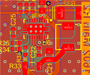
Below is the schematic, and the layout is reasonable, possibly could use a little better GND on the input caps, but there is a full plane and things are pretty tight.

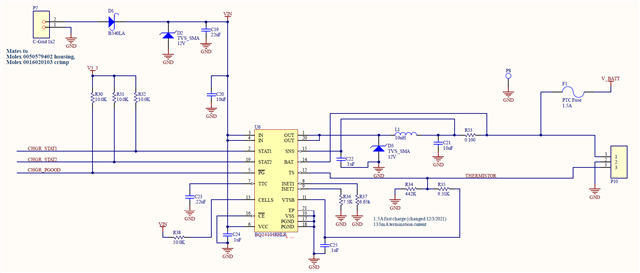
All parts are populated, including the TVS on the output. Input is from a 30W 12V wall supply. V_BATT is the load, P10 is the battery pack connector, P7 is the 12V input.

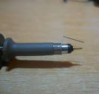
The parts seem to be properly soldered, but it's difficult to be sure since the removal of the part reflows the thermal pad.

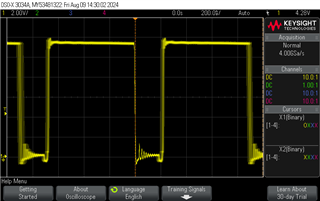
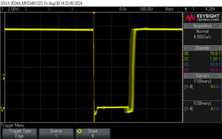
A failed part does nothing when the input voltage is applied, but they do not seem to load the battery, and the TS pin seems to be unpowered, but may be low resistance to GND, didn't check that.

Any ideas?

Best regards,

Craig

  • Hi Craig,

    The only known issue with this IC was ringing at the SW pin outside the abs max but the Schottky diode should prevent that. Can you send your layout, preferably in pdf?  

    Regards,

    Jeff

  • Hi Jeff, thanks for the reply.

    To be clear, that's not a Schottky diode, it's a TVS. The reference design uses a nominal 18V Zener, no doubt to meet the 18V VIN spec, while our design uses a 12V TVS (13.3-14.7V breakdown) since we only have a 12V input and we use the same TVS on the input for protection.

    Here is the layout:

    The layer stackup isn't ideal, with layer 2 being power with the yellow-ish VIN trace under the switching node, but layers 3 and 4 are solid GND in this region.

    Could there be any issue with hot-plugging the battery in during assembly? There is no guarantee that GND mates before + with the connector.

    Best regards,

    Craig

  • Hi Jeff

    In reviewing the details of the TVS, I also notice that there is higher capacitance on the part we're using, like maybe 800pF vs. the 80pF or so of the part in the reference design. That's a lot of capacitance for a switching node, I wonder if that could be the issue, and removing the TVS might solve the issue?

    Craig

  • Hi Craig,

    The layout more or less follows the EVM which is not the best in my opinion.  I usually recommend moving the inductor further away and viaing down and back up to it so that the input cap can be placed across the top of the IC for short connection to IN and PGND pins. This minimizes ringing while switching.

    I now recall that the TVS diode is needed to prevent overvoltage from overshoot ringing on the OUT pins. It provides some protection against undershoot as well.  You can look for the ringing at the OUT pin on a scope using a probe with short ground connect as shown below:

    Make sure the scope is at least 200Mhz and the channel is set to no filtering. If the ringing on the OUTx pulse rising edge or battery hot plug is close to 20V overshoot, then that is the issue. Then the TVS diode is likely too slow to respond, possibly due to the higher capacitance.

    If there is undershoot ringing below ground on the OUT falling edge which switching or at battery hotplug, Schottky diode with lower forward drop than the TVS could help.

    Regards,

    Jeff

  • Hi Jeff, thanks for the prompt reply.

    I'm sure that the input cap can be improved, but I don't believe that that's blowing the parts.

    Measuring the switching node with a well grounded scope actually shows much more ringing on the falling edge when the TVS is populated, no doubt due to the LC tank circuit formed from the diode capacitance. I don't see more than about half a volt overshoot with the TVS, but more falling edge ringing.

    When I remove the TVS, and therefore the capacitance of it, the ringing on both the rising and falling mostly goes away:

    This is with a 350 MHz scope and probe, using a dogleg GND connection, just as you suggest.

    Because we are only doing 12V charging, do you think it's OK to remove the TVS?

    I certainly don't see anything that raises concern in either of these waveforms, so the only thing that I can think of is excess current stress of the switch when the diode and it's capacitance is in there.

    Best regards,
    Craig

  • Hi Craig,

    Per the datasheet, the TVS diode is required. The BQ2410xA and BQ2412x versions were released with fixes to prevent damage that the TVS diode prevented.  Unfortunately, there is not a BQ24104A only a BQ24103A.  Can you change to a TVS with capacitance closer to that on the EVM?

    Regards,

    Jeff

  • Thanks Jeff

    Not without changing the layout. I can go from 1000pF down to about 200pF, but not much lower in the SMA package on the layout.

    I see that on pg 28 of the datasheet, note A says that the BQ24104 does not require the diode, so are we good anyway?

    The measured waveforms look great without the TVS, but I'm not hot-swapping the battery or doing the other odd-ball use cases that may cause issues.

    Craig

  • Hi Craig,

    So it does.  This part is so old that I have no design resources to reach out to.  Give it try without the diode.  I would not expect the diode to damage the IC though since the datasheet strongly implies it is required for the 100, 103, 105, 113.  But the EVMs for those versions do not have the TVS diode.  

    Regards,

    Jeff

  • Hi Jeff

    OK, that's the plan. We're replacing all of the failed parts and removing the TVS.

    I hate that there isn't a good way to know what's causing the failures other than trial and error. We will take one board and stress it with a bunch of battery inserts to see if that causes an issue, can you think of anything else that we can do to confirm that the issue is resolved?

    Craig

  • Hi Craig,

    Unfortunately, no.

    Jeff