Other Parts Discussed in Thread: LM5148
Tool/software:
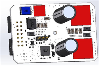
I just made a board with TI’s LM5143 controller where it is configured as an interleaved buck converter where the output is 5.1V @ 10A. I am getting poor efficiency during loaded and even unloaded conditions. At no load the input is 48V @ 100mA and during loaded conditions (2-4Aout) we are about 60% and the mosfets get hot (>80°C with only 30-40% load). I believe it is related to shoot through, but I am not sure how since this device has the adaptive dead time control. I have a current probe hooked up to the input and there is a large current spike with some ringing when the high side turns off and the low side turns on. Everything else seems normal where the duty cycle is properly regulating and there is no oscillation.
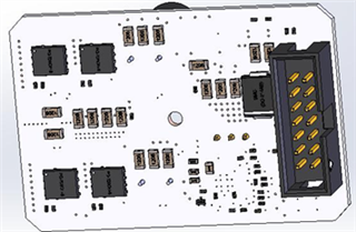
I have attached the schematic where the only change on the schematic and gerber files. Instead of the 10uH for the buck I am using a 6.8uH (the workbench designer recommends a 4.7uH so I might end up with that). All the inductors selected have a much lower DCR than the ones in the workbench designer. The mosfets I am currently using are ISC0602NLSATMA1 for both the top and bottom. I’ve investigated the forums and there are people that are using slower mosfets with this controller, so I am not sure exactly what is going on. The only thing I can think of is there is an issue with the layout where it is impacting the adaptive dead time; however, I see this issue with no load which would lead me to believe is not a noise issue.