This thread has been locked.

If you have a related question, please click the "Ask a related question" button in the top right corner. The newly created question will be automatically linked to this question.

TUSB1046EVM: Multiple Modes Not working: No display port or USB Data

Part Number: TUSB1046EVM
Other Parts Discussed in Thread: TPS65987, TUSB1064

Tool/software:

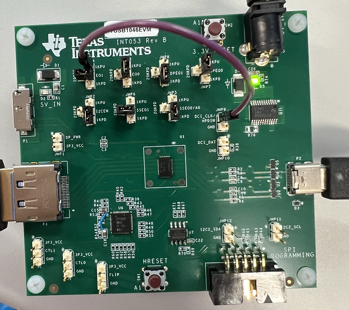
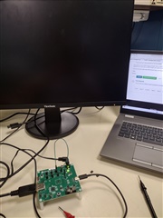
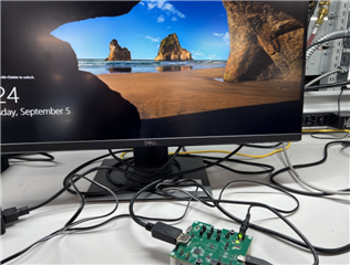
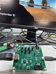
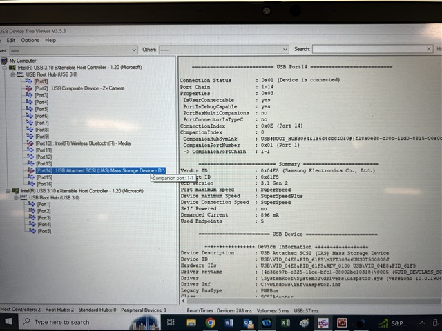
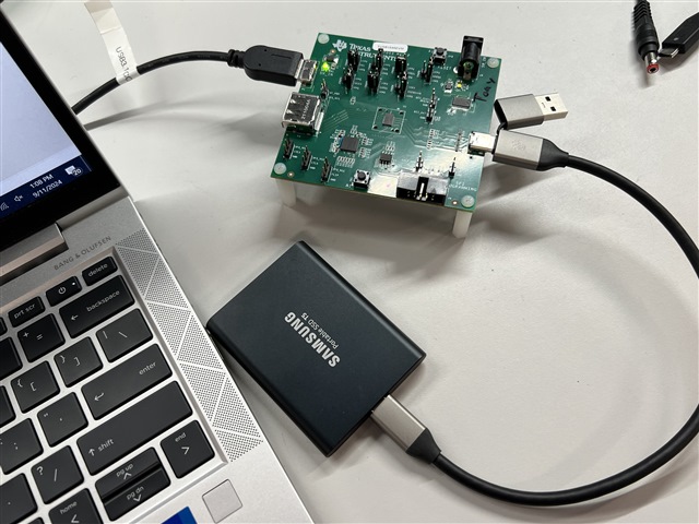
I cannot get USB data nor display port to work. I am attempting to use GPIO mode. I have a rev F TUSB1046EVM

I am using an external 5V supply at J5

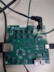
JMP2 is installed horizontal to enable GPIO mode

I tried both installing a header on JMP1 and leaving it open.

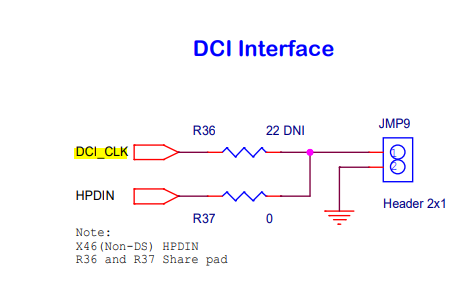
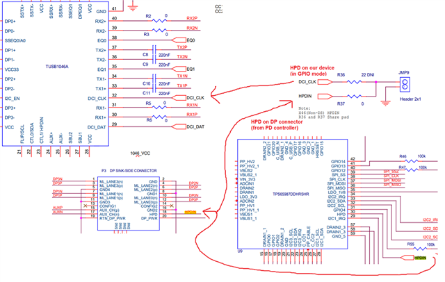
I wired 3.3V directly to JMP9 to force HPD high

R37, R14, R12, R11, R10 and R8 are installed.

R69, R65, R63, R76, R36, R13, R9, R7, R53, R54, R52, R51 are not installed

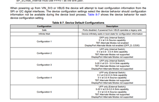
I have tried the following settings using J1, J2 and J3:

  • Display Port 4 mode with no flip
  • Display Port 4 mode with Flip
  • One Port USB 3.1  no flip
  • One port USB 3.1 no flip
  • 1 port USB 3.1 + 2 lane DP no flip
  • 1 port USB 3.1 + 2 lane DP with flip

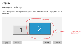
No matter what, I can't get any data nor display port to pass. I can only charge devices using the display port. Please advise if any of my configuration settings are wrong.

  • Hi,

    Can you show an image of the board you're using? I've tested this board in the lab with the following JMP settings and it worked with no issues:

    I've seen a similar situation in this E2E thread. They were trying to pass DisplayPort data specifically, but you should try the debug steps from that thread to see if it will fix your issue.

    Best,

    Shane

  • Hi Shane,

    I copied your settings and received the same results. I also read the other thread and made sure R36 was installed and jumped over the 3.3V.  I have tested with two different EVMS and neither passes Display Port Data or USB data.

    I'm not sure I understand how yours is working. Nothing is controlling the jumpers to set the mode at J1-J3 in the above photo?

  • Hi Tony,

    I have a few questions to get a better idea of your test:

    1. What are the other elements in your setup aside from the EVM board? (Video/USB source/ cable lengths/ video sink...)

    2. Can you confirm that USB data passes correctly without our board in the signal path? Just want to confirm there is not a setup issue.

    3. Are you able to see the display on your DisplayPort source when plugged in through the EVM?

    I'm not sure I understand how yours is working. Nothing is controlling the jumpers to set the mode at J1-J3 in the above photo?

    In GPIO mode, the onboard PD controller will drive FLIP, CTL0, and CTL1. You do not need to populate these jumpers.

    I believe the schematic for this board on TI.com is for an older rev. Let me attach the correct schematic for Rev F here for better clarity: TUSB1046 EVM Schematic Rev F.pdf

    Best,

    Shane

  • I have removed the jumpers and saw a message appear once that said the "Displayport device you connected may be limited" but won't recognize it or connect using the display settings. 

    My setup for display port is HP laptop, HP USB Dock and Viewsonic USB display. I am able to drive the display through the following path: Laptop->USB C-->Dock->Display Port Out-> Viewsonic Display. The Display port cable is about 3 feet. I am trying to get my hands on a mini displayout to display cable so I can drive the monitor/EVM direct instead of through the hub.

    My setup for USB is HP laptop and USB A to C or USB C directly to the cell phone and am able to make a connection and move data. When I connect to the EVM I can charge the phone but receive no data. The USB cables I am using are about 1 foot.

  • Hi Tony,

    Can you try adjusting the EQ settings on the board? If the EQ is too high or low, the USB connection may fail. The settings you want to adjust would be SSEQ1/0 and EQ1/0 for USB.

    As for DisplayPort, you should at least see the display show up on your host. Have you been able to try this without the dock in your signal path?

    The steps for debugging DisplayPort alt mode is to first check that HPD is high (3.3V) on the EVM when a device is plugged in, then check that your AUX common mode voltages are correct. You can probe the AUX lines with a multimeter or scope to see the common mode voltage. AUXp should be between 0 and 0.4V, while AUXn should be 2.7 to 3.6V when the DP sink is attached. 

    Are you seeing HPD go high and the correct AUX Vcm?

    Best,

    Shane

  • I received a mini to normal display port cable and confirmed I was able to drive a monitor directly, completely skipping the hub.

    I measured pin 18 to ground on P3: 0V (HPD)

    I measured between pins 17 and 15: 3.3V (AUXP to AUXN)

    Pin 17 to ground: 3.3V (AUXP)

    Pin 15 to ground: 0V (AUXN)

    Something is amiss

  • To be clear, I cannot drive with the EVM.

  • Some other items I found in my investigation. This dev kit has no pull ups on the schematic for AUX and the TUSB1046 datasheet  calls out a need for them:

    The datasheet also seems to imply that we could connect HPDIN to two different pins when I2C_EN=0 for GPIO mode :

  • More information I read in the TPS65987 datasheet seems to imply I need to load a configuration to flash to allow alternate mode. Is this also required?

  • Hi Tony,

    This dev kit has no pull ups on the schematic for AUX and the TUSB1046 datasheet  calls out a need for them:

    This is ok because the TUSB1046 EVM sits between a DP source and sink. The pullups/downs are only necessary when the 1046 is used directly on the Source side (designed on the DP source board itself)

    The datasheet also seems to imply that we could connect HPDIN to two different pins when I2C_EN=0 for GPIO mode

    In GPIO mode (I2C_EN = 0), the HPDIN pin is pin 32. In I2C mode, the HPDIN pin is CTL1/HPDIN (pin 23). Since you're configured for GPIO mode, the correct HPDIN pin should be pin 32.

    Let me take this board into the lab and test myself. I realize that the board I had sent an image of previously was REV B, so perhaps there is a difference here. I have a REV F board that I will try to pass video and USB data through. Let me get back to you tomorrow on my progress.

    Best,

    Shane

  • Hi Tony,

    I tested this board today and was able to pass video successfully. Here are the board settings I used:

    I had to drive HPD high using a jumper wire on JMP9. Please check that HPD is around 3.3V when plugging in your video sink.

    Here is the setup I made. Video passes from the PC, through the 1046 EVM, and to the monitor through the Type-C port.

    I measured pin 18 to ground on P3: 0V (HPD)

    You need to drive HPD using a jumper wire, or the TUSB1046 will not pass video data. This board appears to be configured for I2C mode by default, so to use this in GPIO mode, you need to drive this pin yourself. Refer to the board image to see which jumper needs to be driven high.

    Can you try your test with HPD driven high and the board settings I used?

    Best,

    Shane

  • Do you have any different resistor populations than default? I made the jumper changes and nothing is making it out to the display.

  • Hi Tony,

    I'm looking at your setup and believe you have the connections backwards. The TUSB1046 is made to be on the source side, so the DP connector needs to connect to a GPU or DisplayPort source. The USB-C port needs to connect to the monitor/DP sink.

    If you want the type-C to go to your DP source, you need to use the TUSB1064, which is designed for a sink-side application.

    Can you try changing the connection and test whether this works?

    Best,

    Shane

  • Unless I'm misreading your statement. I already have it setup right.

    The display port connector is connected to the laptop. The USB C is connected to the monitor.

  • Thanks for clarifying, I suppose the cables in your image go out of view so I was mistaken, my apologies.

    Are you able to at least see the display show up on your DP source? Even if video does not pass through, you should still detect the presence of a display through the HPD signal.

    Best,

    Shane

  • Not sure what's missing here. My PC doesn't recognize another display:

    I did an inspection of my current resistor populations to see if anything is missing:

    Installed: R8, R10, R11, R37

    Uninstalled: R7, R9, R13, R36

    Jumper on JMP9 DCI_CLK

  • Hi Tony,

    I think the issue is that R36 is not installed on your board. R36 connects JMP9 to the HPDIN pin on our device in GPIO mode:

    Can you change the resistor installed on R37 to the R36 position? If I'm not mistaken, I believe these resistors share a PAD.

    If you cannot, do you have a way to drive 3.3V to the R36 pad opposite JMP9? This should at least let the source see your display.

    It seems the board you have may be configured for I2C mode by default. I suspect this is why R36 is not installed, as R37 would be the correct path for the I2C mode HPD signal

    Best,

    Shane

  • Hi Shane, I moved the resistor from R37 to R36 and that unfortunately did not do the trick

  • Hi Tony,

    Is the pad on R37 driving high (3.3V) when a display is plugged in? The PD controller should be driving this signal high when a monitor is plugged in to the type-C port. Perhaps something is preventing this.

    For context, the connection from R36 is the HPD signal for our device in GPIO mode. The connection from R37 is the HPD signal of the upstream DP connector. Due to the way this board was designed, these are two separate nets that both need to be driven high. One for our device, and one for the upstream connected DP source:

    If the PD controller isn't driving this signal, something may be affecting the CC ALT mode negotiation over the type-C port. Out of curiosity, is the connected display providing VBUS on the type-C cable in your setup, or is the VBUS only coming from our board? VBUS should be sourced from our board.

    Best,

    Shane

  • There is no voltage on the R37 pad. As for VBUS, I have an external power supply so the board should be providing VBUS. I see D5 and D2 lit. If I only connect just the external power supply and remove all cables, I still see D5 and D2 lit. D5 makes sense to me, D2 does not. I'm seeing about 2V at the anode.

  • Tony

    If you have a USB cable connected to P1, please do not provide an external 5V on J5 as this will drive 5V back into the USB host VBUS pin, possibly damaging it.

    The external 5V is only needed if you are doing a DP only testing. 

    For the DP only testing.

    1. R7, R9, R13 un-populated

    2. R8, R10, R11, R12, R14 populated

    3. R36 and R37 should both be populated then you don't need the external jumper wire as the HPD from the PD controller will drive TUSB1046 HDP/DCI_CLK

    4. Leave USB unconnected on P1

    5. Have external 5V provided on J5

    6. DP cable connected to P3

    7. Type-C cable connected to P2 

    8. Use a multi-meter check the voltage on the middle pin of J1. J2, and J3. You should see J1 and J2 both at 3.3V, and J3 either 0V or 3.3V. 

    9. If you flip the Type-C cable, then you should see the middle pin of the J3 change from 3.3V to 0V, or from 0V to 3.3V. This confirmed the PD controller is working

    10. Check pin 1 of JMP9, it should be 3.3V, indicating PD controller driving the HPD high

    11. You should see the Type-C display at least being recognized

    If you don't see the display working, then I would like to swap the EVM with you and see if it solves your issue.

    Thanks

    David

  • Thanks David, I confirmed the resistor populations as described above:

    When installing the USB cable:

    J1: 0V

    J2: 3.3V

    J3: 3.3V

    When flipping:

    J1: 0V

    J2: 3.3V

    J3: 0V

    JMP9 pin 1: 3.3V

    No display output or display recognized. Even though JMP9 pin 1 is high, since J1 is measuring 0V it seems like the controller is not recognizing DP mode and staying in USB 3.1 mode only. Doesn't seem like the chip is damaged though, since the FLIP worked. What else can cause DP not to work?

  • Hi Tony,

    It seems like the issue may be with the PD controller configuring our part. FLIP (J3) and CTL0 (J2) seem to be correct, however J1 and HPD should be pulling high when a connection is made. Are you able to ship the EVM board here so David and I can take a look at it in our lab?

    The shipping address is:

    David Liu,

    Texas Instruments, Inc.

    12500 TI Blvd.

    Dallas, Texas 75243

    If this is not possible, you can try setting the '1' position on J1 to forcefully drive this high. Please also check that HPD is driving high with R36 and R37 populated.

    Best,

    Shane

  • Hi David,

    I will get this shipped out to you in the morning and will provide tracking status when I have it. 

    I forced J1 high and saw no change. I don't see HPD driving high on its own.

    With this board, there is a damaged pad on R36, but I was able to solder a wire to the exposed copper. I measured it and the signals are connected.

  • The FEDEX tracking number is: 7782-8076-0368

  • Thanks Tony,

    I see this will arrive 9/3, and will update you when I have the board.

    Best,

    Shane

  • Hi Tony,

    Still waiting on the board to arrive. Seems like it may not show up by 5 today (given its already 4:30) but will keep you updated when it gets here.

    Best,

    Shane

  • Hi Tony,

    We've received the board and will test in the lab.

    Best,

    Shane

  • Hi Tony,

    After testing the board you sent, it appears the PD controller firmware is not configured correctly. The firmware you had on the PD controller was setting HPD correct, however it was not setting CTL1 high. Because CTL1 is our video-enable pin, this causes video to not pass through the board.

    In testing, I found that the board you sent can pass video once CTL1 is pulled high with a jumper:

    David and I are looking into why the default firmware you received does not drive CTL1 with the PD controller team. I'll keep you updated with the progress.

    Best,

    Shane

  • Thanks Shane. I assume the firmware is something we don't normally have to update and is what comes from the factory

  • Hi Tony,

    Yes this is correct. The firmware should support USB and video straight out of the box.

    I'm writing up a new firmware file that seems to work for both CTL1 and HPD on the 1046EVM I have here in the lab. Let me load this onto the board you sent and test to be sure it works there as well.

    Best,

    Shane

  • Hi Tony,

    Today I tested the EVM board you sent with the new firmware. Video was able to pass without externally driving CTL1, so the PD controller operates as expected here.

    I remember you mentioned not being able to pass USB data. I'm testing this here in our lab, and I see that the PD controller configures our device correctly for USB, but does not always supply VBUS to the downstream device. I suspect this is why USB data isn't working.

    Let me look into this to be certain both USB and video will pass.

    Best,

    Shane

  • Hi Tony,

    I tested USB on this board with 6 different devices and they all worked except the one I used yesterday. I think the issue was with that specific SSD, not the board. 


    Now that both USB and DisplayPort are working, I can ship this board back to you. What's a good address to return the board to? If you'd rather not disclose this on the public E2E forum, you can accept my friendship request and send me a private message.

    Best,

    Shane

  • I setup the repaired unit this morning. I confirm that USB is working. However, Displayport is not. Is there some reason why this would be incompatible with this display?: ViewSonic VA2447-MHU, 24" 1080p MVA Monitor with HDMI and USB-C

  • It does think its driving at least CTL 1: 3.3, CTL0: 0, FLIP: 0 and then when flipping CTL 1: 3.3, CTL0: 0, FLIP: 3.3

  • What voltage do you see on HPD? (JMP9)

  • Its good that HPD and CTL1 are being set correctly. Do you see the display appear on your PC?

  • No, the PC does not recognize the display. I just get "We didn't find another display"

  • Hi Tony,

    I've just confirmed this board works to pass video with two different PCs and monitors:

    Dell U2719D monitor + Dell XPS 8700 PC

    Dell P2720DC monitor + HP Prodesk 600 G5 PC

    This may be an issue with your monitor, PC, or the DisplayPort/USB-C cables you're using. Are you able to try a different combination of PCs/monitors/cables?

    Best,

    Shane

  • I have tried three USB C cables. They all connect between the laptop and phone through the dev kit no problem. I also can drive another monitor directly from the laptop with the displayport cable I am using. So that leaves me with just the monitor being incompatible. I don't have another USB C monitor so I'll have to get my hands on another one.

  • Tony

    Is your connection

    DP source -> TUSB1046 EVM - Type-C Monitor?

    Thanks

    David

  • Yes. Laptop is driving display port to P3. Then The EVM is connected P2 directly to the Type C monitor. I put the monitor earlier in the chat and have re-copied it here: https://www.viewsonic.com/us/va2447-mhu-24-1080p-100hz-monitor-with-freesync-premium-usb-c-and-hdmi.html?srsltid=AfmBOop69qaGQx3uPaRdK4PiDwNRQDc8g7nBcM1CJvr73oNiJMQ-lji8 Any reason, why it can't drive this monitor?

  • We went out to Best Buy and bought a thunderbolt USB C Cable rated for 40GBPs. Now it is passing display port data! I guess the cables we had couldn't handle the higher display port speeds.

  • Glad to hear! Let us know if you see any other issues with the board.

    Best,

    Shane