Other Parts Discussed in Thread: BQ79616
Tool/software:
In the previous post, it was believed that the power regulator failure was a one off event but it has since been discovered that this is a recurring issue. After replacing the board in the failed battery, the system worked properly for several days and then without any warning experienced the exact same failure as the previous board. More information was gathered with this occurrence and is outlined below. Any help in diagnosing why this is happening and what is causing it to happen is greatly appreciated.
Problem Behavior
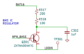
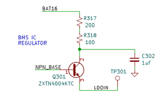
Capacitor C302 and BJT Q301 front the power regulation circuit below become extremely hot and the BQ79616 becomes inoperable. This behavior persists until power is removed from the board/chip but does not appear to return immediately upon reconnecting the board to the battery stack. When in the failed state, capacitor C302 measured over 190F with an IR temp gun and Q301 measured over 130F. Heat could be felt rising from the board and it smelled of overheating electrical components. The output voltage of the BJT was 3.85V.
| Ref | Description | MPN |
| C302 | CAP, CERM, 1uF, 100V, +/- 10%, X7R, 1210 | C1210X105K101T |
| Q301 | TRANS NPN 150V 1A TO252 | ZXTN4004KTC |
| R317 | RES, 200 OHM, 1%, 2010, SMD | RMCP2010FT200R |
| R318 | RES, 100 OHM, 1%, 2010, SMD | RMCP2010FT100R |
Problem Scenario
The board in question was operating normally for some period of time (days/weeks). The chip was addressing properly and communicating without any apparent issues. Upon powering the host controller and attempting to address the stack chips, the chips failed to address and the first stack chip exhibited the overheating capacitor and BJT issues. The second stack chip did not present with these issues but of course was not addressed due to the failure of the chip before it. (This system does not implement the ring architecture) When the issue occurred, the chip should have been in a sleep state. Once the problem occurs, the problem persists and the chip becomes non-responsive and inoperable until physically disconnected from the battery stack.
This exact issue is confirmed to have occurred twice. Both times in the same battery module and both times it was the first stack board which failed. The issue is suspected to have occurred 3 additional times but in each of those 3 cases the boards were replaced before testing for overheated components and the issue did not re-occur.
First Occurrence Testing / Troubleshooting
- The problem board was removed from the battery and tested for failed components.
- The C302, Q301, R317, and R318 were all found to be within manufacturer spec and showed no signs of failure.
- When connected to a benchtop power supply in a testing environment, the board functioned properly and the BQ79616 addressed properly with no apparent issues.
- 60V was applied across BAT0 and BAT16 and the board connected to a host via via the cap isolated serial lines.
- There was no excessive heating of any components during this test.
- C302 showed no deviations in continuity nor capacitance versus a known good part.
- Q301 did not exhibit any signs of damage or defectiveness. Q301 was functional during bench tests.
- There were no measured continuity issues between any of the BAT0 / GND and any other BAT pins on the boards.
Second Occurrence Testing / Troubleshooting
- The problem board was removed from the battery and allowed to cool.
- The problem board was reconnected to the battery stack while not mounted in the battery to determine if the components would overheat while the board was "free hanging"
- There was no excessive heating of any components on the board
- The metallic standoffs used to mount the board were attached to either side of the board to test the theory that the ground plane was being pinched and causing the issue. The board was still "free hanging" and otherwise not mounted into the battery and was totally isolated minus the cell tap connections.
- There was no excessive heating of any components on the board
- The board was remounted into the battery and the stand offs intentionally overtightened to test the theory that the standoffs are the root of the issue.
- There was no excessive heating of any components on the board
- The board now addressed and functioned without issue.
- The BAT0 pin was intentionally shorted to the metallic standoffs and the aluminum battery enclosure to test if this would cause the issue.
- There was no excessive heating of any components on the board
- The board now addressed and functioned without issue.
- The system was power cycled and addressed 15+ times and exhibited no issues.
Ideas and Theories
- The C302 capacitor is shorting to ground and sinking an excessive amount of current causing the BJT not to function properly and the BQ79616 to become unresponsive.
- Metallic mounting hardware leads to a scenario where the board is shorted and problem behaviors occur.
Useful / Relevant Information
- System architecture is comprised of a single host board with a BQ79161 acting as a COMM transceiver connected to one or more stack boards via a twisted pair wire with cap only isolation.
- BAT voltage to the stack chips is between 44V and 68V depending on battery state of charge.
- Stack chips are fully populated with all 16 cell voltage connections and 8 GPIO connections to thermistors.
- C302 is oversized based on the Ti reference schematic which suggests a 0.22uF capacitor.
- C302 is a single capacitor and not two capacitors in series as is suggested in the Ti design reference.
Questions
- Would a short to GND of C302 cause the BJT to become non-functional?
- What scenarios other than a short to GND would cause the C302 and Q301 to overheat even in a sleep or shutdown state?
- Where would we look schematically to find a potential design issue?
- Could C302 being oversized (1uF) versus the 0.22uF in the design reference cause any issues?
- Is it an issue that C302 is just a single capacitor and not two capacitors in series, as suggested by the Ti design reference document, cause any issues?
- Can you think of a scenario where a High Voltage isolation issue somewhere else in the battery or vehicle would cause an issue?
- Why would this exhibit as an intermittent failure and be very difficult (so far impossible) to reproduce?
- Do you have any ideas on how we can intentionally replicate this issue in a testing environment?
- Is there any logical explanation as to why the problem seems to occur either on startup or shutdown?
Known Design Issues
- It has been noted that R320 should not be populated. The issue has occurred on boards that both did and did not have R320 populated.
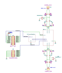
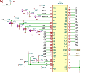
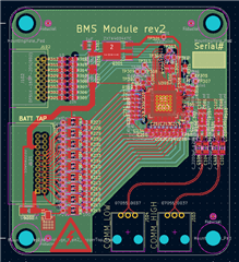
Schematics