This thread has been locked.

If you have a related question, please click the "Ask a related question" button in the top right corner. The newly created question will be automatically linked to this question.

BQ24610: Issue with BQ24610 Not Charging 24V Lead-Acid Battery

Part Number: BQ24610

Tool/software:

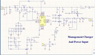
I am writing to seek clarification on a problem I am having with the BQ24610 IC in a 24 V lead-acid battery-charging application. I've carefully set up the circuit in line with the indications on the datasheet. However, the charging does not begin as expected, and I've noticed that the STAT1 pin remains LOW.


Setup Details:

  • Voltage Input: 28V
  • Battery Type: 24V Lead-acid
  • Recharge Voltage (Vrecharge): 25.99V
  • ISET1 - Fast Charge Current: 1
  • Precharge/Termination Current (ISET2): 0.3A

Information from the Datasheet:

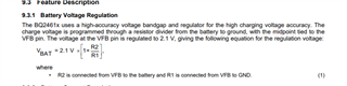
  • Reference Voltage (V_FB): 2.1V
  • Recharge Voltage Offset (V_RECHG): 0.050V
  • Recharge Voltage: From this formula, I calculated R220 and R226 values to have a recharge voltage of 25.99V.
  • Charge Voltage: The datasheet indicates the charging voltage, which may vary between 2.1V and 26V.
  • Fast Charge Current (ISET1): Set to 1.1A. Resistors R112 and R116 are adopted to derive the required voltage on the ISET1 pin.
  • Precharge/Termination Current (ISET2): 0.3A is set using R211 and R215 for the necessary voltage at the ISET2 pin.
  • Switching Frequency: Set to 600kHz to ensure high conversion efficiency.
  • Timers: I have not used a function of the timer, because the pins of timers are connected to the ground GND to disable this function.
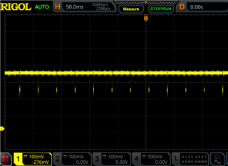
The Problem:

After the settings above described and with everything in the datasheet, the charger does not begin working while the battery voltage goes down to 24V. It is set so that the charger should begin acting if the voltage goes below 25.99V, as stated in the specs, but that is not the case.


Observations:

It is most likely that the STAT1 pin is in the LOW state-a sign that the battery will be charged or is completely charged. Since the voltage from the battery reads 24.2V, it should be in charge mode. The circuit shows no other fault indications, and recharge voltage is set to 25.99 V, which should be enough to start recharging when the battery voltage drops below this level. I would greatly appreciate your guidance on whether there is an issue with the settings or if additional steps should be taken to activate the charging process.


  • Hello Fadi,

    I have a few questions:

    Do you have a system load? Do you see any change if you remove system load/

    What is the battery voltage when you begin charging? Do you see any change if you lower battery voltage?

    What is the voltage on REGN?

    Best Regards,

    Christian.

    1. Hello Christian,

      I wanted to provide a summary of the issues I am encountering with the BQ24610 charging circuit:

      • Input Voltage Behavior:

        • When applying an input voltage of 28V or 27.9V without any load, I observe rapid flickering on the PG LED. This flickering starts when the input voltage ranges from 25.9V to 28V. However, when the voltage drops back to 25.8V, the PG LED stabilizes and remains consistently on in a low state.
      • STAT1 Behavior:

        • STAT1 activates immediately when the circuit is powered on without any load.
        • When a load is connected and the power is interrupted, then restored, STAT1 does not reactivate, and the PG LED continues to flicker.
      • REGN Voltage:

        • The voltage on the REGN pin is measured at 5.97V.
      • Battery Voltage:

        • The battery voltage during charging is 24.2V.
        • There are no significant changes observed when varying the battery voltage.

      I hope this summary provides a clear picture of the issues I’m facing. I appreciate your continued support and look forward to your guidance on resolving these issues

      Additionally, I would like to inquire if you have had the chance to review the design of my circuit to ensure that everything is set up correctly according to the datasheet.

      I appreciate your continued support and am looking forward to your guidance on the next steps

  • Hello Fadi,

    Can you provide a scope capture of the VCC pin and the PG pin? when the PG pin is flickering.

    What is max charge voltage of the battery?

    I also recommend using a 6.8uH inductor with 20uF output cap.

    Best Regards,

    Christian.

  • Hello Christian,

    Thank you very much for your response. I replaced the inductor and the capacitor as you recommended. The max charge voltage I intend to use is 26V, in line with the datasheet. Please take a look at the attached pdf that shows the PG and Vcc readings at two different Vcc points, showing the flickering behavior I mentioned at two different Vcc points. You can additionally refer to the schematic I posted above.

    Best regards,

    Fadi

    scope captures.pdf

  • Hello Fadi,

    I'm reviewing the scope capture and will provide feedback after I gather more information.

    Best Regards,

    Christian.

  • Hello Fadi,

    I'm confussed why you set the recharge voltage to 25.99V if the max voltage is 26V.

    Your resistor divder set the battery voltage regulation to 26.6V, which is higher than the maximum battery voltage.

    I recommend changing this resistor divder.

    Best Regards,

    Christian.

  • hello christian 

    after doing  recommenditions that you suggest, the PG blinking still have the same problem please find the attched screen shoot of PG voltage 
    powr supplay 30 volt 
    VCC 28. V
    REGN 6 V
    VFB 2.12 V
    ACSET 0.69 V
    ISET2 0.24 V
    ISET1 0.21 V
    BTST   27 v


    Best Regards,

    Fadi

  • Hello Fadi,

    after doing  recommenditions that you suggest, the PG blinking still have the same problem please find the attched screen shoot of PG voltage 

    Is the device charging as expected?

    Can you try using a 10kohm pull up resistor to adapter for the PG signal?

    Best Regards,

    Christian