Because of the Thanksgiving holiday in the U.S., TI E2E™ design support forum responses may be delayed from November 25 through December 2. Thank you for your patience.

This thread has been locked.

If you have a related question, please click the "Ask a related question" button in the top right corner. The newly created question will be automatically linked to this question.

BQ25798EVM: PCB copy doesn't charge and can't be programmed with USB2ANY

Part Number: BQ25798EVM
Other Parts Discussed in Thread: USB2ANY, BQ25798

Tool/software:

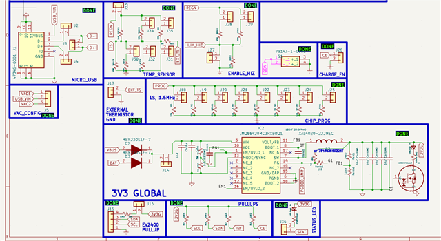
Hello! I created a copy board of the BQ25798EVM but instead of the LDO for PULLUP I placed a TI LMQ66420MC3RXBRQ1 Buck converter. The 2 problems are that:

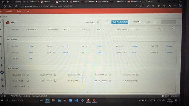
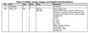
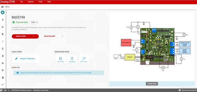
1 - When I connect the EVM copy to the USB2ANY and then to the PC GUI, it DOES say "Connected", BUT whenever I try to "Read all registers" I see a signal on my oscilloscope, but nothing happens and no values update! I configured the shunts for a 1S, at 1.5MHz, and I tried to set the "Charge Voltage" from 4.2V default to 3.9V so many times, yet the chip doesn't seem to store these values. Because after a power cycle when I try to read the values again, it always says 4.2V (same for any other changed field). Also the ADC doesn't read anything even if I have voltage on VAC1 or VBUS:

     

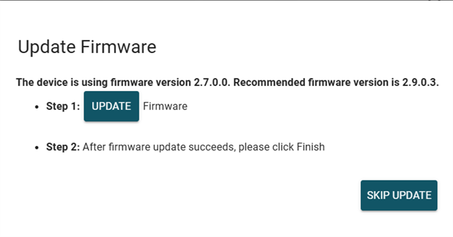
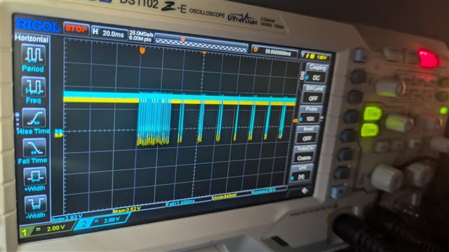
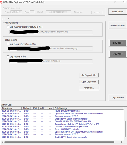
Also one more strange thing, on the USB2ANY explorer it says I must have the 2.7.0.0 version, whereas in the GUI it says I must have 2.9.0.3. I currently have 2.7.0.0 and skip version on the GUI every time because other wise I couldn't use the USB2ANY explorer. Also note, the only time it works to save the data on the chip is when I am connected to the USB2ANY both in the explorer AND in the GUI. Then I can change some fields and they will be remembered IF I power cycle the EVM copy within like 1-3 minutes? If I wait longer even this method fails and it forgets everything I wrote to it. Though it does always send I2C messages to the chip. Here's a "Read all registers" signal:


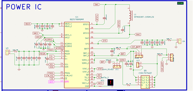
2- even though I followed all the steps in table 1-3 from the EVM datasheet, added a 5V-3A bench power supply to VIN and added an actual battery to BAT, it doesn't charge the battery! I set up all the shunts as in the datasheet and here's the schematic of my PCB:


My Application: I want to make a Sodium-Ion battery charger. I chose the BQ25798 because I saw I can change the charge voltage. The voltage needed to charge a sodium-ion is 4V or 3.9V and the minimum (completely dead voltage) is 1.5V.

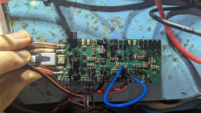
Here's how the PCB looks:

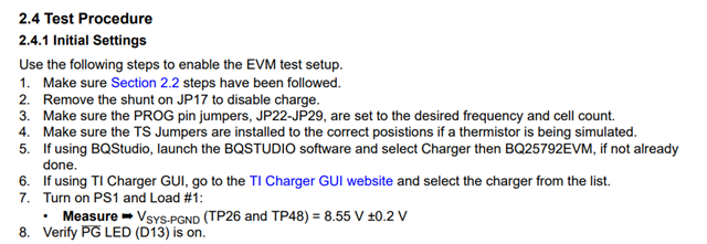
Notice the CE shunt is not installed because I followed the steps from the image below. For PS1 I have a bench adjustable power supply and for Load #1 I have my Sodium-Ion battery directly hooked up to Battery and GND. I don't measure VSYS-PGND 8.55V but 1.75V, and PG LED is not on.

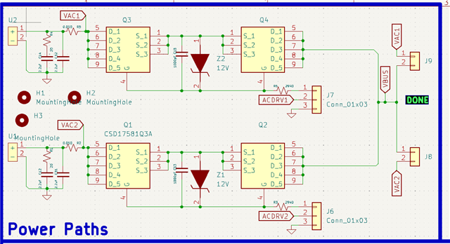
All components solder joints have been verified and they're installed correctly. I used any input voltages between 5 and 15V. Nothing worked. VBUS is 3.8V regardless of what voltage I place within that interval. It's strange that out of 15V only 3.8 get out of the 2 mosfets... Maybe this could be the problem as to why it doesn't charge at all, because the voltage at VBUS is just way too small. Should I try and bypass the mosfets? They're a protection feature after all

First, I'd like to say I HEAVILY appreciate any kind of feedback as I've been having this issue for some time!

So, do you know how I need to program the chip using USB2ANY? Maybe I am doing something wrong or I'm missing a step?

Also do you spot any issue in the schematic? Or why isn't it charging? Could it be that small voltage at VBUS? If yes what component could be the problem? I assume the mosfets?

UPDATE 1:
If I connect the SHUNT on JP3 VAC1 to VBUS I do get VBUS = VIN1 = VAC1 (Tried with 9V). Now it's no longer stuck at 3.8V! However Vsys is still always 1.75V (was before as well), and even with the CE SHUNT on, the battery still doesn't get charged...

  • Hello Foco,

    I recommend reading the Datasheet and EVM user guide

    1 - When I connect the EVM copy to the USB2ANY and then to the PC GUI, it DOES say "Connected", BUT whenever I try to "Read all registers" I see a signal on my oscilloscope, but nothing happens and no values update! I configured the shunts for a 1S, at 1.5MHz, and I tried to set the "Charge Voltage" from 4.2V default to 3.9V so many times, yet the chip doesn't seem to store these values.

    The charger does not have memory, so the registers value will reset during a power on reset. You will need an host device to write the registers values to the BQ25798 after it powers up.

    . Also the ADC doesn't read anything even if I have voltage on VAC1 or VBUS:
    You don't have the ADC enabled.

    Can you enable the ADC, and try again. You will have to read registers after enabling ADC.

    Best Regards,

    Christian.

    Best Regards,

    Christian.

  • Hello Mr Christian and thank you so much for telling me it doesn't have a memory because I tried so many ways to try and make it remember!

    I will try and turn on the ADC tomorrow and now I am no longer at the office. After that it should be able to read VBUS/VAC1 and all the other values on the chip when I press "Read all Registers", right? If so that's great! I will keep you updated!

    Also, what about the charging? How can I make it charge my battery? You said there must be an external MCU or something to load the I2C commands to the chip on power cycle, but how do I get the I2C commands and what MCU can I use? Does an ESP32 work because it's 3.3V logic. Where can I see the I2C commands to send it to the chip via the ESP ? Also how do I actually enable the charging? Because with the battery and PSU connected, it doesn't charge.... Do I have to send an I2C command, along with having the CE pin shunt mounted?

  • Hello Foca,

    I also recommend disabling the watchdog timer while testing.

    I will try and turn on the ADC tomorrow and now I am no longer at the office. After that it should be able to read VBUS/VAC1 and all the other values on the chip when I press "Read all Registers", right? If so that's great! I will keep you updated!

    Yes, it should.

    Also, what about the charging? How can I make it charge my battery? You said there must be an external MCU or something to load the I2C commands to the chip on power cycle, but how do I get the I2C commands and what MCU can I use? Does an ESP32 work because it's 3.3V logic. Where can I see the I2C commands to send it to the chip via the ESP ? Also how do I actually enable the charging? Because with the battery and PSU connected, it doesn't charge.... Do I have to send an I2C command, along with having the CE pin shunt mounted?

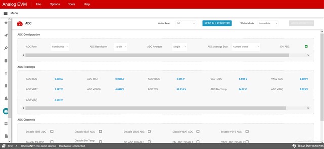
    After you capture the ADC values, can you provide the screen capture? it will make it easier to understand why it is not charging.

  • I tried to press the "EN ADC" button and it doesn't turn on. I click on it and it doesn't get checked. I can still see a signal on the oscilloscope. What can we do now Mr Christian? What could be stopping to from turning on?

    I also tried with both the 2.7.0 and the 2.9.0 firmwares, none worked. Voltage is 3.3V with SDA, SCL and GND connected. Here's some images of the signal I get when I try to enable the ADC

    And I did turn off the watchdog.

    Also here's a screen capture of the window:

    By the way, I noticed the USB2ANY has internal 1.5K pullup resistors to the internal 3.3V, whereas my board has 10K pullup on SCL/SDA. Could this double pullup be roblematic and thereby I should remove the resistors on my PCB?

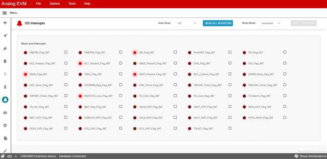
    Also this is what I see in interrupts when I first connect the PCB to the computer, because if I press "READ ALL REGISTERS", these values get erased and all buttons shut down (no longer red):

  • MAJOR UPDATE: FIXED THE I2C Communication

    Well, as the title says, I fixed the I2C communication and I can now finally TRULY "READ ALL REGISTERS" and enable the ADC. 

    Method: I installed a new chip, then fiddled with the shunts by connecting and disconnecting some stuff, then realized the REGN pin was shorted INTERNALLY to GND, then installed back the previous chip and checked for the REGN short, it didn't have it (R.I.P. previous one). At first this one didn't work either, but then I fiddled with its position and re-soldered the ship like 3 times until I saw the PCB was now drawing 6mA of current at 5V, unlike it was previously drawing just 1mA. So I knew something changed.

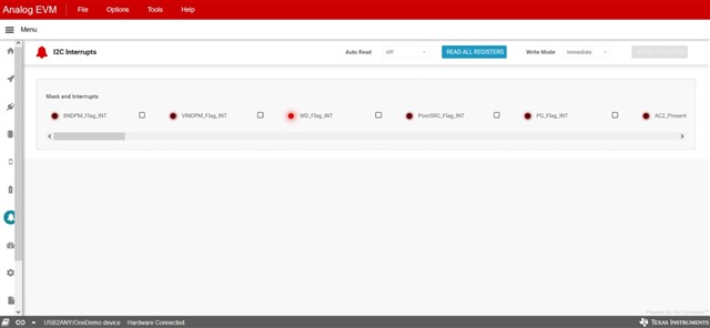
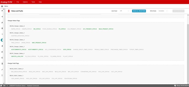
    Then I updated the USB2ANY to the version suggested in the GUI (2.9.0.something) and it worked! I could enable the ADC, read the values, and all of that. Also I could now read all the interrupts/faults without erasing them from the GUI (the red dots would disappear after trying to read all registers). Here are the screenshots:


    Is everything alright? Should I be able to charge now? (I haven't tried) By the way I'm using Firefox and that's why the interrupts tab is displayed weirdly. The only interrupt ON was the WD_Flag_INT, but after 5 minutes I came back to it, read again and it disappeared. 

    By the way I used the EXACT Shunts configuration as in the EVM datasheet. And now I am finally reading good values:

    VBUS/GND = VAC1/GND = Literally VIN1 (tested with 5.8V)

    Vsys/GND = 4.05V (This one doesn't change regardless of VIN

    So is there any problem you see in the chip status in those images? Should I be able to charge? By the way, it will charge at the values I enter in the GUI, not on the ones I selected on the PROG pins, right? ( I mean I used 1S/1.5MHz, but by default I think it's 4.2V for Li_Ion But I need 3.9 for Sodium-Ion). What has priority? What's written on the chip via I2C or the settings on PROG made with shunts? I assume what's selected on PROG must be roughly the same as what you program in the GUI? (Like if it's 1S, leave it at 1S and the switching frequency is set only by the shunt?)