This thread has been locked.

If you have a related question, please click the "Ask a related question" button in the top right corner. The newly created question will be automatically linked to this question.

BQ25750EVM: BQ25750EVM

Part Number: BQ25750EVM
Other Parts Discussed in Thread: BQ25756EVM, BQ25756, BQSTUDIO, BQ25750, EV2400

Tool/software:

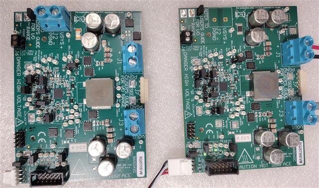
We bought BQ25756 EVM boards for battery charge and discharge test.  We then found BQ25756EVM board could not provide power from the battery in reverse mode to regulates the SYS terminal voltage once VAC_in is removed. We then bought BQ25750EVM board. However, the BQ25750EVM board even could not perform the battery charge. Do you think the BQ25750EVM board does not work, or damaged at the first place? Any hint or suggestion for trouble shooting of BQ25750EVM board? By the way, the setup in our test between BQ25756EVM and BQ25750EVM is almost the same except for selecting the different EVM board after launching bqStudio GUI.
Thanks,

Jimmy

  • Hello Jimmy,

    Thanks for working with us on this. I've got a few questions to help us debug.

    What's your battery and input voltage?

    What's your charge current set at and what is your test setup?

    What register settings are you using?

    Best Regards,
    Ethan Galloway

  • Hi Ethan,

    We use LiFePO4 24V 24Ah battery. The VAC input voltage is 28V and charge current at 5A.

    We bought BQ25750 EVM board and EV2400 board. We follow the EVM user's Guide to perform the test.

    Now the battery charge is successful. But we have trouble in reverse mode.

    We would like to have the charged battery as power supply and regulates 24V battery voltage to 28V SYS terminal voltage after 28V VAC input is removed. The discharge current could be 15A.

    Could you provide us a register setup file to implement the test scheme as described above?

    Thanks,

    Jimmy

  • Hello Jimmy,

    For your condition, I think the auto reverse mode on the BQ25750 will work well. You can check this FAQ page for a summary of reverse mode

    I recommend the following register settings for this test condition:

    Watchdog = Disabled
    VSYS_REV=28000mV
    EN_AUTO_REV=1
    All other registers are default

    With auto reverse mode, reverse mode will activate once VAC drops below the ACUV threshold and supply 28V to the system.

    Let me know if you have any questions about this and let me know if you are still having trouble with this.

    Best Regards,
    Ethan Galloway

  • Hi Ethan -- We tried what you suggested for those registers settings, but not work.

    Basically, we use bqStudio GUI to setup 28000mV, the register 0x0C reads back value is 0x15E0, and SYS_LOAD voltage is 25.4V (charged battery voltage value), not the expected reverse voltage value 28V after VAC_in is removed. 

    register setting.txt
    * Created: Mon Sep 16 09:33:38 PDT 2024
    *
    * Format: Register Name  tab Character,\t  Register Address  tab Character,\t  Hexadecimal register value.
    * BQZ Container: Charger_2_00-bq25750.bqz
    *
    Charge Voltage Limit	00	10
    Charge Current Limit	02	190
    Input Current DPM Limit	06	640
    Input Voltage DPM Limit	08	348
    Reverse Mode Input Current Limit	0A	1E0
    Reverse Mode System Voltage Limit	0C	15E0
    Precharge Current Limit	10	140
    Termination Current Limit	12	A0
    Precharge and Termination Control	14	0F
    Timer Control	15	0D
    Charger Control	17	C9
    Pin Control	18	C0
    Power Path and Reverse Mode Control	19	23
    MPPT Control	1A	20
    TS Charging Threshold Control	1B	96
    TS Charging Region Behavior Control	1C	57
    TS Reverse Mode Threshold Control	1D	40
    Reverse Undervoltage Control	1E	20
    VAC Max Power Point Detected	1F	00
    Charger Status 1	21	0C
    Charger Status 2	22	80
    Charger Status 3	23	02
    Fault Status	24	00
    Charger Flag 1	25	01
    Charger Flag 2	26	00
    Fault Flag	27	00
    Charger Mask 1	28	00
    Charger Mask 2	29	00
    Fault Mask	2A	00
    ADC Control	2B	60
    ADC Channel Control	2C	02
    IAC ADC - Use Field View	2D	00
    IBAT ADC - Use Field View	2F	00
    VAC ADC	31	00
    VBAT ADC	33	00
    VSYS ADC	35	00
    TS ADC	37	00
    VFB ADC	39	00
    Gate Driver Strength Control	3B	00
    Gate Driver Dead Time Control	3C	00
    Part Information	3D	02
    GM Adjust	61	30
    Reverse Mode Battery Discharge Current	62	02

    Above is the setting register value file. Could you help to check what is wrong in our setting? Or could we have an online meeting so yo can directly instruct us what we should do?

    Thanks,

    Jimmy

  • Hello Jimmy,

    Thanks for being patient with this. We'll get back to you later this week.

    Best Regards,
    Ethan Galloway

  • Hi Ethan -- We now can perform the battery charge/discharge scheme test.. The case can be closed. Thanks for your support and time.

  • Hello Jimmy,

    Ethan is out of office, so I will be taking over this question.

    I have a few question:

    Do you have a system load, or are you just measuring the voltage at the terminal?

    Can you enable the ADC, and provide the register information again?

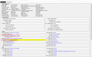
    In the register logs that you sent, the battery is in taper mode, and Reverse mode is off. Can you confirm the adpater is not present? I'm not sure why it would be in taper mode if adapter is not present.

    Best Regards,

    Christian

  • Hi Christian -- Thanks for stepping in to help. I am out of office for the rest of week and will provide information to you next Monday.

    Jimmy

  • Hi Jimmy,

    Let us know if there is any update here.