This thread has been locked.

If you have a related question, please click the "Ask a related question" button in the top right corner. The newly created question will be automatically linked to this question.

BQ76952: SCD

Part Number: BQ76952

Tool/software:

Dear TI,

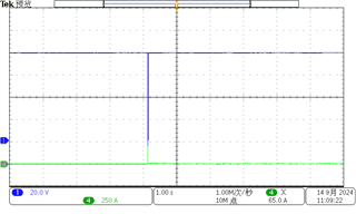
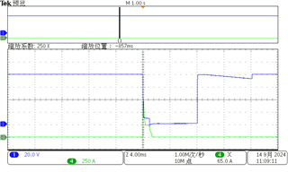
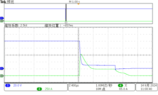
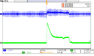
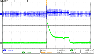
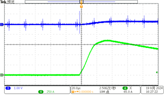
Recently, we were debugging the SCD functionality of BQ76952 and encountered some issues. We used a large instantaneous current (250A  within 400us) to trigger the SCD, but we found that the instantaneous current did not trigger the SCD normally.And then when we used a slower rising current(250A  within 0.5ms), it did. As shown in the following picture:

instantaneous current:

 slower rising current:

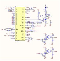
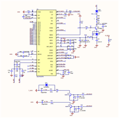
Our configuration is as follows:

Protections:SCD:Threshold->6 = 125mv

Protections:SCD:Delay->28

Protections:SCD:Recovery Time->30

Looking forward to your prompt reply.

Best Wish

  • Hello Gong,

    Are you measuring the voltage between the device pins by chance? If not, could you try to take waveforms there, and see? There is a chance the device is not seeing the instantaneous current you’re injecting from where you are measuring.

    Best Regards,
    Alexis

  • Hi Alexis,

    I refer to this answer to solve the problem:

    But it didn't seem to help

    I changed the resistance value of the galvanic resistor, now it is 0.167mR(3*0.5), and the short-circuit current is 815A as shown in the attached figure. In addition, the output voltage is also measured synchronically. The interval from output closing to re-opening is 8.1ms, and the short-circuit protection action takes about 1ms. why?

    Time reference 1s 

    blue is output voltage 

    green is current 

    Best Wish

  • Hello Gong,

    Can you please share your schematic?

    Best Regards,
    Alexis 

  • Hi Alexis,

    Thanks for reply,We using FET in Test Mode ,and here is the schematic for 2 BQ76952 in series:

    By the way, to use SCD function, besides Enable Protection A, CHG FET Protection A, DSG FET Protection A and SCD. Is there any other registers need to configurate? And here is our configuration:

    Protection A -> 0xFC

    CHG FET Protection A  -> 0x98

    DSG FET Protection A  -> 0xE4

    SCD : Threshold->6   Delay->28  Recovery Time->30

    Best Wish

  • Hi Zhang,

    I strongly recommend observing the voltage between the SRP and SRN pins as the device acts on that measurement. The RC filters on the pins might be changing how the device sees the current so it important to get an accurate idea of what the device is seeing.

    Regards,

    Max Verboncoeur

  • Hello Max Verboncoeur,

    Thanks for reply,here is the image:

    CH1 blue :the voltage between the SRP and SRN pins

    CH4 green:short-circuit current 

    Looking forward to your prompt reply.

    Best Wish

  • By the way, We found that with the body diode protection turned off, the SCD can trigger normally with probability,do you have any idea?

  • Hi Zhang,

    That is very interesting. Body diode protection shouldn't make a difference in this case. It only applies to when one FET is off, and the device sees current that would flow through its body diode.

    Just to double check, have you recalibrated the CC Gain and Capacity Gain settings for your sense resistor value? I'm curious if the device is not measuring the current correctly.

    Regards,

    Max Verboncoeur

  • Hi Max,

    I have not recalibrated the CC Gain and Cap Gain; But I think the device can measure the current correctly. When we load the battery , the current value get from the device are the same as and the load value set.

    Finally,what about the waveform that we measured the voltage between the SRP and SRN pins in the last last reply,Is it any problem?

    Best wish.

  • Hi Zhang,

    The new waveforms are a little difficult to read since the vertical scale on the SRP-SRN voltage is so large. 1V/div makes it difficult to see what the voltage level is on the signal.

    Looking back at your earlier waveforms, this looks like the device reset caused by an SCD transient that you found another E2E explaining. Since you mentioned that a slower ramping current does not experience this, I want to focus on that possible root cause.

    Did you populate C54 and C55 on your schematic? Have you captured a waveform of SRP-VSS and SRN-VSS to see if the transient is there and if adding the capacitors suppressed it?

    Regards,

    Max Verboncoeur