TPS2373-4EVM-758: TPS2373-4EVM-758

Part Number: TPS2373-4EVM-758
Other Parts Discussed in Thread: UCC2897A, , TPS2373

Tool/software:

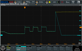
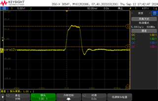
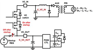
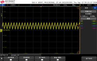
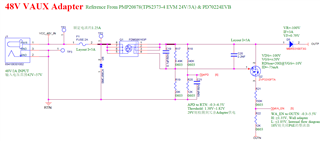
Hello, currently I use TPS2373-4 with UCC2897A to build a PD module that supports 60W bt. Now the detection and classfication waveform of PD are normal, consistent with the evaluation board TPS2373-4EVM-758. However, the waveform of VC_IN and VC_OUT is abnormal, causing UCC2897A to work abnormally, and the active clamp forward converter has no output. When I remove the two diodes(D9 & D10) and directly add 12V voltage at the VC_OUT, the output of UCC2897A is still abnormal. At this time, PIN12 will periodically output 50ns 12V pulse wave. Please help me troubleshoot what the problem is,THANKS.

TI_PD_FAE_20240905.pdf

  • The PDF is my SCH, the BR+ and BR- is from a bridge output(44~57V)

  • My design is referred to the TPS2373-4EVM-758

  • Hi Hao,

    Thanks for reaching out!

    TPS2373-4 only has VDD-RTN, VC_IN, VC_OUT and PG working with the UCC2897A. If you can measure the PG pin which should be high and provide VC_OUT=12V externally, UCC2897A should work when UVLO (VDD-RTN bus voltage though a divider) is reached.   

    I took a look on the TPS2373-4 part and did not see a major issue. D15 may be not necessary and you can make it unmounted. If no PG and VDD-RTN issues, I would recommend you to reach out to the UCC2897 experts. 

    Let me know if you want to transfer this question to UCC2897 and I can help you transfer. 

    Best regards,

    Diang

  • The waveform of PG is shown in the above figure.

    "Let me know if you want to transfer this question to UCC2897 and I can help you transfer. " It's OK

  • The PG‘s  waveform is unnormal, The EVM's PG is 5V.

  • The AUX and APD sch is

  • Hi Hao,

    I am in time bank leave and will back on 17th/spet. I will get back to you in the next week. Thanks for your patience. 

    Best regards,

    Diang

  • Thank you, looking forward to your answer.

  • Hi Hao,

    Thanks for your patience.

    The PD signal looks like a triangle wave. It could be caused by SS/SD's charge/discharge rather than TPS2373-4. Since TPS2373-4 PG pin only has two status: tie to RTN (not good) or High impedance (good). Tie to RTN should cause much faster PG drop slew rate (a straight line in 50ms/div view).

    I would feel it could be more related to the AC forward is not working as normal. I will forward you to the UCC2897 experts and I will keep my eyes on this thread too in case there are any questions about TPS2373-4.

    Best regards,

    Diang  

  • Hi,

    Usually this type of debugging is to disconnect UCC2897A from TPS2373 then use an external bias voltage to UCC2897A VDD pin with the bias voltage 14V. Please do this then to find if UCC2897A converter normal and if it is normal then the issue is not from UCC2897A. I am not understanding where PG PD, etc connected to UCC2897A, if these are input signals to UCC2897A, then you have to check why these source signals are bad. 

    If UCC2897A does not operate normally after you separate UCC2897A from TPS2373, then describe what you see so we can go from there.

  • I have tried this situation and still haven't sovled the problem.Lastely, It was found that UCC2897A has overcurrent protection. When the sampling resistor is short-circuited to ground, it can work normally. However, when I switch between PoE and Adapter power supply, it is easy to burn out the MOSFET(Q5) transistor.

  • Hi,

    Please provide the current waveform and indicate where the waveform measured.

    Also provide your ucc2897A converter schematics.

    Where is Q5 in your circuit, please provide its converter circuit, and provide its Vgs, Vds, and its drain current before and after switch to PoE.