- Ask a related questionWhat is a related question?A related question is a question created from another question. When the related question is created, it will be automatically linked to the original question.
This thread has been locked.
If you have a related question, please click the "Ask a related question" button in the top right corner. The newly created question will be automatically linked to this question.
Tool/software:
Good morning
As you advised, I ordered two boards of the PMP40586 type to start studying my project as indicated in the thread 'UCD3138128A: UCD3138'.
Putting aside all the hardware modifications needed for the low voltage section, I would like to understand how to connect the two boards in parallel using the 'DPWMA0, SYNC, TCAP' pins.
Are there any application notes or other materials that cover this topic?
Best regards
Gianluca
Hello Gianluca,
Linking the previous thread: https://e2e.ti.com/support/power-management-group/power-management/f/power-management-forum/1399822/ucd3138128a-ucd3138
The PMP40586 CONTROL schematic shows the ISHARE circuit. The ISHARE looks to be connected to AD02 pin and PWM0 pin.

The PMP40586 mainly uses the existing UCD3138FW_LLC code. In the ADC initializations (init_adc12), AD02 is initialized as the ISHARE pin. The PWM0 pin is also used for ISHARE control.
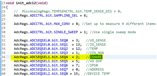
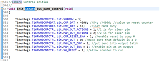
You can view the standard_interrupt.c void handle_current_sharing_master_slave(void) function to see how the UCD handles the current sharing.
Regards,
Jonathan Wong
Hi Jonathan,
thanks for the response, but I have a few more questions for you.
The first is about the ISHARE signal. I saw that this signal goes to the J5 connector on the board, but which pin on the SLAVE board should I connect it to? Another question,
I read your article 'How to parallel two DC/DC converters with digital controllers,'(slyt748) and it mentions that in order to achieve interleaving and
simultaneous startup, the DPWM0A, PWM0, and GPIOx pins on the master board, and the GPIOx, TCAP, and SYNC pins on the slave board need to be used (figure 1).
My question is: can these pins simply be connected to each other, or is there additional hardware required on the board?
Thanks a lot.
Gianluca
Hello Gianluca,
You can also use the same ISHARE signal pin. Think of the ISHARE signal pin as the LS pin on a load share controller, such as the UCC29002. You can find the application diagram of the UCC29002 on the first page of the UCC29002 datasheet.
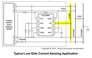
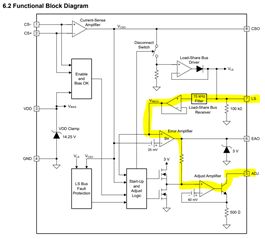
Just like the LS pin, you will connect your ISHARE pin to as many other ISHARE pins as you desire on parallel power supplies. The UCC29002 uses its LS pin to balance the load across all parallel power supplies using analog components, as shown in the block diagram on page 7 of the datasheet. The UCD code that I shared above basically implements the same block diagram but uses firmware instead.
The "How to parallel two DC/DC converters with digital controllers" (slyt748) is meant for PSFB supplies and syncing the DPWMs. The article also describes using passive-droop current sensing instead of active current sharing using a current share (LS) bus. The PMP40586 uses the active current sharing method.
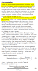
The active current sharing is quite different and does not use the Controller ⇒ Target configuration (TI no longer prefers to use "master/slave" terminology). I would first try to learn how the UCC29002 analog load share controllers work and then see how the UCD code implements the load share via firmware. The UCC29002 block diagram is a good starting point.
Regards,
Jonathan Wong