Other Parts Discussed in Thread: BQ34Z100, EV2400, BQSTUDIO, USB2ANY, BQ25750, , BQ25756, BQ25756EVM
Tool/software:
Has this been resolved? If so, can you post the recommendation?
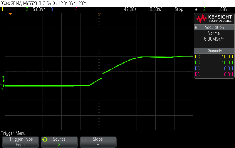
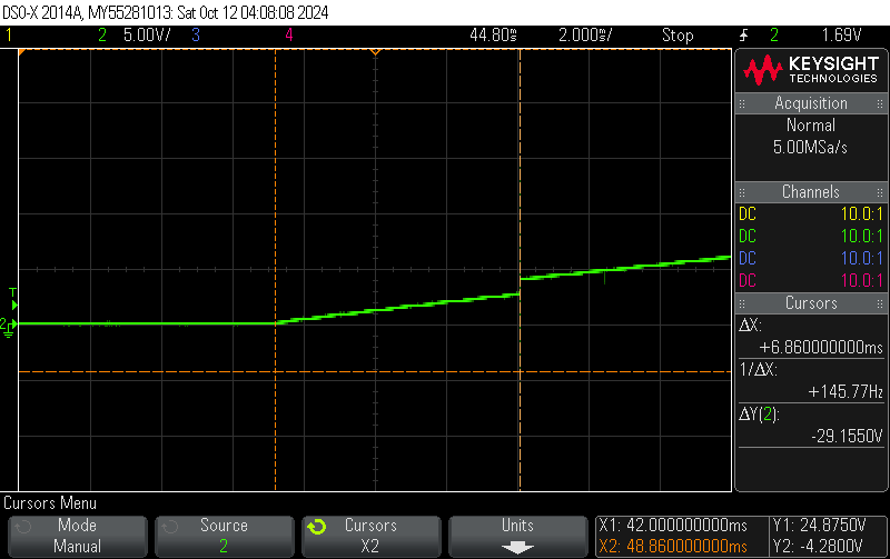
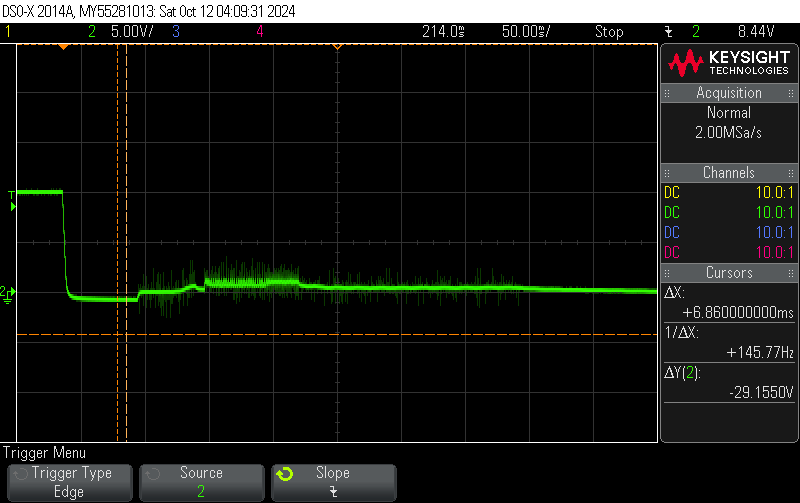
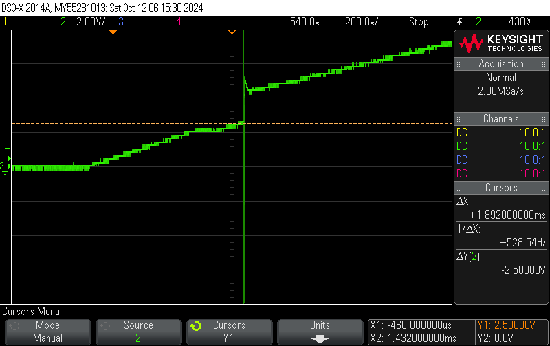
We are using a 48V nominal battery with a max of 54.4V. We have damaged an EVM and our custom board when VIN is applied and the battery is connected. It caused a burn on the PCB near the battery charger IC on the VSYS and VIN pins on our custom board.
Is there anyone that I can send our schematic to for feedback to see if this is the same issue?
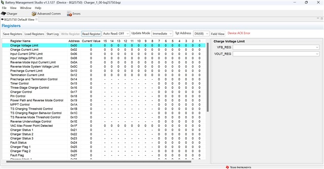
So far, we have not been able to get I2C working on multiple computers through Battery Management Studio or the TI charger GUI using the EV2400 with the EVM or our board. Very frustrating. It seems most of the responses from TI on similar issues are to "try a different computer". However, we are able to establish communication with a BQ34Z100 EVM through the same setup.