This thread has been locked.

If you have a related question, please click the "Ask a related question" button in the top right corner. The newly created question will be automatically linked to this question.

TPS6594-Q1: PMIC TPS6594133A-Q1 inductor questions

Part Number: TPS6594-Q1

Tool/software:

hello sir,

when we design TPS6594133A-Q1, we have some confused about inductor value. In app note, table 4-1 recommend all inductor value is 220nH. 

Powering Jacinto 7 SoC For Isolated Power Groups With TPS6594133A-Q1 + Dual HCPS.pdf
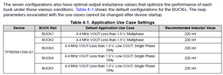
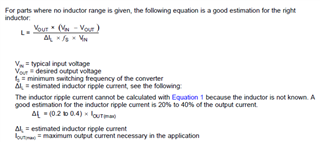
My question is,  if we follow below formular to calculate inductor value, there are much different according to actual load current. For example, in 4.4MHz, 0.85V/900mA load current condition, we calculate typical inductor is 586nH, maybe can select actual inductor is 680nH. Much difference compared the recommended value! If follow EVM value 220nH, is the ripple will be much bigger and exceed 20%Iout load current. So, how to understand which one result is correct?
  • Hello Xin,

    My question is,  if we follow below formular to calculate inductor value, there are much different according to actual load current. For example, in 4.4MHz, 0.85V/900mA load current condition, we calculate typical inductor is 586nH, maybe can select actual inductor is 680nH. Much difference compared the recommended value! If follow EVM value 220nH, is the ripple will be much bigger and exceed 20%Iout load current. So, how to understand which one result is correct?

    The one in the User's Guide is correct. That equation does hold true, but there are assumptions made with it. It assumes that the BUCK is only used PWM for it's gate control & that it is the sole contributor to the output voltage/current. So please use what is in the guide as that equation does not hold true in this case of the PMIC.

    Adding additional inductance into the feedback loop will cause instability.

    Best Regards,

    Nicholas

  • According to your explain, we discuss in below conditions.

    1. In only PWM mode, we follow equation value to design.

    2. In only PFM mode, we should use recommended value from guide? If without recommeded value, how we calculate this value?

    3. In both PWM and PFM mode, we should use recommended value from guide?

  • 1. In only PWM mode, we follow equation value to design.

    2. In only PFM mode, we should use recommended value from guide? If without recommeded value, how we calculate this value?

    3. In both PWM and PFM mode, we should use recommended value from guide?

    By default the device starts off in Auto mode on all BUCK outputs which require the recommended value from the guide. Deviating from this can add inductance to the control loop leading to false OV/UV conditions leading to shutdown.

    Recall that not all of the BUCKs are in single phase, BUCKs 1 & 2 are in multiphase, these PDN-3X have been validated and can ensure performance when adhering to recommended values.

    BR,

    Nicholas McNamara

  • Thanks for your reply.

    1. Here I'm curious, how to calculate the inductor and to choose proper inductor if TI without any recommend?

    2. This PMIC TPS6594133-Q1 start from auto mode, in operation mode, PMIC operate in FPWM mode?? You mentioned OV/UV, this in start step occur or normal operation? What about BUCK ripple question? How to evaluate if it's good or not?

    3. From my point, previous we follow TI formuar to calculate inductor, now, I'm very confused. For other BUCK, should we follow this formular to select proper inductor or not?

    4. Could you tell me how to calculate loop stability? Acutually, now, phase margin and gain margin we can't calculate without app note to guide. Only can calculate ripple according to TI app note formular, it seems also only in PWM mode.

  • Hello Xin,

    1. Here I'm curious, how to calculate the inductor and to choose proper inductor if TI without any recommend?

    The proper inductor is the one recommended by TI by the switching frequency outlined in the datasheet. It is what is adhered, that if you choose the inductor based upon that you will achieve these metrics of ripple DC accuracy etc. The compensation loop expects either 470nH, 220nH, or 1000nH, so there is no straight forward equation to calculate for the inductance, please use the recommendations.

    2. This PMIC TPS6594133-Q1 start from auto mode, in operation mode, PMIC operate in FPWM mode?? You mentioned OV/UV, this in start step occur or normal operation? What about BUCK ripple question? How to evaluate if it's good or not?

    The PMIC does set the BUCKs to be FPWM mode. OV/UV is enabled when the BUCK is enabled on the PMIC for safety coverage, it is a part of normal operation. The question of evaluation of good or not, is more of, is it in recommendations based upon the datasheet, is it within the datasheet specifications?

    3. From my point, previous we follow TI formuar to calculate inductor, now, I'm very confused. For other BUCK, should we follow this formular to select proper inductor or not?

    In short, no, please use the recommendations outlined in the datasheet and user's guide. Was it for this product or another part number? Each IC has their own compensation based upon internal and external components. 

    4. Could you tell me how to calculate loop stability? Acutually, now, phase margin and gain margin we can't calculate without app note to guide. Only can calculate ripple according to TI app note formular, it seems also only in PWM mode

    Allow some time to respond back if we have any documentation available with this.

    BR,

    Nicholas McNamara