Other Parts Discussed in Thread: BQ2050H, BQ34Z950, BQ40Z60, BQSTUDIO, GPCCHEM, EV2400, BQ20Z65, BQMTESTER, BQEVSW
Tool/software:
Hello,
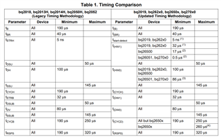
I am evaluating the BQ40z50 as a potential battery gauge in my design. Actually, the BQ2050H is exactly suitable for our purposes, however the temp rating does not meet our standards and the BQ40z50 is listed as the latest version of this product. I have a removal battery pack which only exposes three lines, +, -, and HDQ. I believe this battery pack contains a BQ34z950 but the designers have only exposed the HDQ interface. I am trying to conclude whether or not the BQ40z50 is suitable for a host-side battery gauge design, to me it seems it is suitable for both battery and system-side (as the previous model 40z60 is listed as implementing both...) however I have some questions.
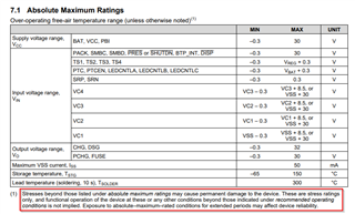
- What to do with VC1 if unused? Datasheet does not specify.
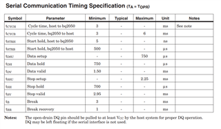
- What to do with the SMBus lines? Can this be attached to the host or is it intended to attach to the battery? Is the BQ40z50 able to implement SMBus protocol with only results of the Impedance Track algorithm?
Thank you for any assistance you may be able to provide.