This thread has been locked.

If you have a related question, please click the "Ask a related question" button in the top right corner. The newly created question will be automatically linked to this question.

BQ4050: Power management forum

Part Number: BQ4050

Tool/software:

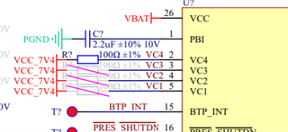
Hello, I would like to ask if the schematic design of BQ4050RSMR meets the requirements. The uploaded file is the schematic. Could you please help review it? Our product is in the design and sampling stage and will be mass-produced later. Please assist us. Thank you.

Best regards.

02. Battery_BQ4050RSMR.pdf

  • Hello,

    Can you please clarify on what kind of cell formation is being used here? if only one cell is being used, then VC1 will need to be the connection point. VC4 cannot be used without VC3, VC2, and VC1 in use.

    Also, I see that the CHG and DSG pins are connected to test points. Is it intended that this application will not be using a FET system?

    In this schematic, is VBAT the connection to the application load?

    Regards,

    Anthony

  • Hello,Anthony


    The battery we use is “UFX 605080-2S”,Please refer to the specification sheet,The battery is packaged in a battery pack with only two wires, and the battery pack is labeled as 7.4V, 3000mAh, 22.2Wh.

    We are not planning to use FET systems. Regarding FET, I would like to inquire if it is a charging and discharging circuit.
    VBAT is the power supply for BQ4050, which is directly supplied to the circuit from the battery. I see that the power supply range of BQ4050 includes the voltage of the battery.
    Also, I would like to inquire if SMB BUS has a voltage level of 1.8V? Because it involves how many volts of IIC should I use to connect.


    Best regards.


    Future

    6153. Battery_BQ4050RSMR.pdf605080-2S(3000mAh)7.4V加板电池规格书.pdf

  • Hello,

    The battery we use is “UFX 605080-2S”,Please refer to the specification sheet,The battery is packaged in a battery pack with only two wires, and the battery pack is labeled as 7.4V, 3000mAh, 22.2Wh.

    Understood, I believe this will be an issue because since there is only two wires, this would need to be treated as one cell. If there is 7.4V going directly to any VC pins, this will be above the voltage thresholds of the pin and can potentially damage the device:

    If possible, we would recommend having a connection to both of the cells in the pack and attaching them from VSS to VC1 and VC1 to VC2 respectively. 

    We are not planning to use FET systems. Regarding FET, I would like to inquire if it is a charging and discharging circuit.

    Understood, please confirm that the protection functionality of this gauge is not looking to be used since many of the protections use the FETs to protect the cell.

    Also, I would like to inquire if SMB BUS has a voltage level of 1.8V? Because it involves how many volts of IIC should I use to connect.

    Yes, I believe this device uses 1.8V SMBus:

    Regards,

    Anthony

  • Thank you very much Anthony.