This thread has been locked.

If you have a related question, please click the "Ask a related question" button in the top right corner. The newly created question will be automatically linked to this question.

TLC5973: Assistance Needed for Implementing Precise Microsecond Delay for TLC5973 LED Driver

Part Number: TLC5973

Tool/software:

Dear Support Team,

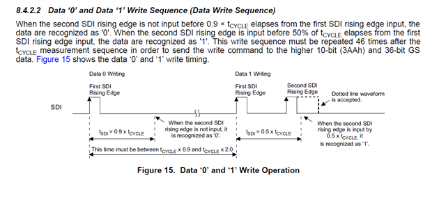
I am currently working on a project involving the TLC5973 3-channel 12-bit LED driver. I am facing some challenges while implementing the precise timing requirements for data transmission, particularly with the delayMicroseconds() function. The TLC5973 datasheet specifies that the timing for writing a '0' or '1' bit must adhere to specific constraints based on the cycle time (t_CYCLE).

Specifically:

  1. When writing a '0', the second rising edge should occur no sooner than 0.9 × t_CYCLE from the first rising edge.
  2. When writing a '1', the second rising edge should occur within 0.5 × t_CYCLE from the first rising edge.

I need assistance with implementing an accurate delayMicroseconds() function to meet these requirements. I would appreciate any guidance or recommendations you can provide for:

  • Achieving precise microsecond delays using either busy-wait loops or hardware timers.
  • Any example code or library recommendations that could be used to implement such precise delays on a microcontroller.

Additionally, if there are any specific considerations or configurations for using the TLC5973 with standard microcontrollers, please advise.

in below i write a code please check.
#define CASCADE_NUM 1
#define WRT_CMD  0x3AA
void led_test(void)
{
GSout0[0]=0X666;
GSout1[0]=0x666;
  GSout2[0]=0x666;
for(Device_j=0;Device_j<CASCADE_NUM;Device_j++)//N-1 cascaded device data
{
    SDI_Data=(((uint64_t)WRT_CMD)<<36)+(GSout0[Device_j]<<24)+(GSout1[Device_j]<<12)+GSout2[Device_j];
    for(bit_i=0;bit_i<48;bit_i++)//write Data
        {
    if((SDI_Data>>(47-bit_i))&(0x0001))
            {
                PORT.P8 = 2;// GPIO high
                for(delay_u32 = 0 ; delay_u32<7;delay_u32++);//1us delay
                PORT.P8 = 0;//GPIO low
                for(delay_u32 = 0 ; delay_u32<7;delay_u32++); //1us delay
                PORT.P8 = 2;// GPIO high
                for(delay_u32 = 0 ; delay_u32<7;delay_u32++);//1us delay
                PORT.P8 = 0;// GPIO low
                for(delay_u32 = 0 ; delay_u32<35;delay_u32++); // 5us delay
            }
            else
            {
                PORT.P8 = 2;//GPIO high
                for(delay_u32 = 0 ; delay_u32<7;delay_u32++);//1us delay
                PORT.P8 = 0;//GPIO low
                for(delay_u32 = 0 ; delay_u32<41;delay_u32++); // 6us delay
            }
}
        for(delay_u32 = 0 ; delay_u32<63;delay_u32++); // 9us delay
}
return;
}