This thread has been locked.

If you have a related question, please click the "Ask a related question" button in the top right corner. The newly created question will be automatically linked to this question.

BQ25750: Software control to start charging with the BQ25750

Part Number: BQ25750
Other Parts Discussed in Thread: BQSTUDIO, BQ25758, EV2400

Tool/software:

I'm a firmware engineer, and I want to use the BQ25750 to charge my battery. What steps should I take to start charging with the BQ25750?

Here are the steps I'm currently following to start charging with the BQ25750. I'm not sure if these steps are correct.
  1. Check EN_CHG=1
  2. Setup CE = low

After following these steps, I didn’t measure any charging voltage at the charging output (all other BQ25750 registers remain at their default settings).

  • Hello Yanjie,

    Thanks for working with us on this. Can you answer a few questions to help us debug this?

    • Are you using the EVM or a custom PCB?
    • Can you read what the status and flag registers say? It might be easier to use BQStudio to this.
    • What's the voltage on VAC and VBAT and what's the specified charge current?

    By the way, we do have have an example driver for the BQ25750 that may help with writing the firmware.

    Best Regards,
    Ethan Galloway

  • I previously used a MCU to write/read Reg values, so I followed your suggestion to use the BQ2400 & Battery Management Studio to retrieve the BQ25750 Reg values.

    My response is as follows:

    • Are you using the EVM or a custom PCB?
      • Custom PCB
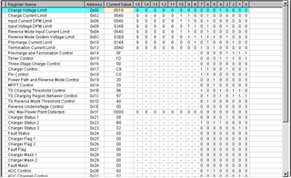
    • Can you read what the status and flag registers say? It might be easier to use BQStudio to this.
      • I use BQ2400 & Battery management studio to get BQ25750 Reg
    • What's the voltage on VAC and VBAT and what's the specified charge current?
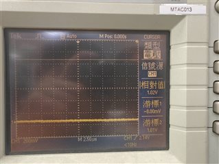
      • As Picture

    In my understanding, if I set up the Reg and Pin correctly, I should be able to measure the charging voltage, even without connecting a battery. So my current goal is to configure the Reg and Pin to enable me to measure the charging voltage

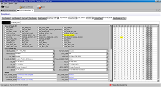
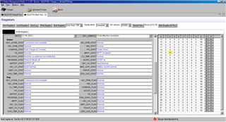
  • The config of my field view are as shown in the image below.

  • Hello Yanjie,

    Thanks for the new information. I'm looking at your registers in field view.

    What voltage are you seeing on VBAT and REGN?

    Also, can you set EN_CHG=1 and send me what the registers report then? Can you also send me your schematic so I can review it?

    Best Regards,
    Ethan Galloway

  • Hi Ethan,

    We need to go through an internal discussion before we can provide you with the schematic, so we’re unable to share it at the moment.

    The voltage at the REGN pin is 5V. I'm not sure if this is what you’re looking for.

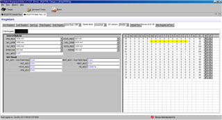
    The image below shows the registers report and the VBAT value when EN_CHG=1.

    Thanks,

    Yanjie

  • Hello Yanjie,

    I think most likely something is wrong with the FETs or inductor. There's a few tests that may be helpful:

    • Make sure that the switching FETs are soldered correctly on the board.
    • Measure the voltage on SW1 and SW2 with an oscilloscope.

    Can you also send me the FET datasheet? When using REGN to power DRV_SUP, we recommend using FETs with a VTH of around or lower than 2V.

    Best Regards,
    Ethan Galloway

  • I'll have the hardware engineer review your description to confirm the details you've mentioned.
    By the way, since we plan to use the BQ25750 to charge batteries with different cell counts, we need the BQ25750 to support various charging voltages. We intend to achieve this by switching different resistor combinations (RBOT, RTOP, etc.) to set the desired voltage. We plan to use relays or transistors to switch these resistor combinations. Could you advise whether this approach is feasible?

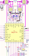
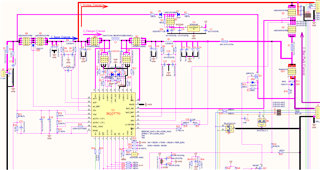
  • Your hardware engineer would like assistance in reviewing whether the circuit design involving the BQ25750 has any issues, as shown in the diagram.

    If you could provide a description or key details from the diagram, I can help with an analysis based on that information. Alternatively, if you have specific aspects of the design you're concerned about, let me know so I can address them directly.

  • Hello Yanjie,

    We intend to achieve this by switching different resistor combinations (RBOT, RTOP, etc.) to set the desired voltage. We plan to use relays or transistors to switch these resistor combinations. Could you advise whether this approach is feasible?

    This will work. If you need to charge a lot of different types of batteries, you could move to the BQ25758. The BQ25758 is an I2C controlled DC-DC converter with CC and CV loops.

    Alternatively, if you have specific aspects of the design you're concerned about, let me know so I can address them directly

    Thanks for this information. I have a few recommendations:

    • For testing, I would short the gate resistors.
    • Make sure D4 and D5 are schottky diodes

    If you measure SW1 and SW2 with an oscilloscope, do you see any switching? Does REGN come up to 5V when charging is enabled?

    Best Regards,
    Ethan Galloway

  • The experimental results based on your suggestion are as follows:

    For testing, I would short the gate resistors.

    No change.

    Make sure D4 and D5 are schottky diodes

    Sure

    If you measure SW1 and SW2 with an oscilloscope, do you see any switching?

    No measurements were taken because there was no output.

    Does REGN come up to 5V when charging is enabled?

    5V alive

  • This is our complete schematic. Please help us review it for any potential issues. The pins connected to the MCU(M0516) have been disconnected and are now controlled manually. The I2C is connected to the EV2400, allowing the EV2400 to operate the BQ25750.

    3580.SCH.pdf

  • Hello Yanjie,

    Thanks for the information. Here are my thoughts on the whole schematic:

    • The ICHG or ILIM_HIZ resistor will need a RC filter in parallel with them if the resistance is greater than 5kΩ.
    • I recommend putting place holders for an RC filter from BATDRV to BATSRC and also from ACDRV to ACSRC
    • R6, R7, R8, and R9 will need to 10Ω resistors.

    Here's the schematics and layout checklist for reference: https://e2e.ti.com/support/power-management-group/power-management/f/power-management-forum/1322803/faq-bq25750-schematic-and-layout-checklist

    Let me know if you have any more questions about this.

    Best Regards,
    Ethan Galloway

  • HI Ethan,

    Here’s the response:

    • The ICHG or ILIM_HIZ resistor will need a RC filter in parallel with them if the resistance is greater than 5kΩ.
    • I recommend putting place holders for an RC filter from BATDRV to BATSRC and also from ACDRV to ACSRC

    Our hardware engineer believes that the two suggestions are related to EMC issues, but my current problem is that the circuit is not functioning—there's no PWM output.

    R6, R7, R8, and R9 will need to 10Ω resistors.

    I tried it, but it didn't help.

    Our hardware engineer reviewed it and found that there isn't much difference compared to our schematic.

    Our expectation was that, based on the previously mentioned software and hardware configuration, after powering on the BQ25750, we would see a PWM waveform on the HIDRV1/2 and LODRV1/2 pins. However, after measuring, we found no such waveform.

  • Hello Yanjie,

    Thanks for the test information. You should see a PWM waveform on SW1/SW2 when the charger is fast charge mode.

    Your engineer is correct that the RC filter for ICHG is for noise issues. However, the RC filter for BATDRV slows down the BATFET turn ON if needed.

    I have a few more test suggestions:

    • Can you check if the ACFETs have turned ON? You should be able to check this by measuring the voltage on the drain of Q6. Do you the VAC voltage VSYS when adapter is plugged in?
    • Can you check the waveform on LODRV1 and LODRV2?
    • Can you also measure the voltage on VBAT during these tests?

    Best Regards,
    Ethan Galloway