Because of the Thanksgiving holiday in the U.S., TI E2E™ design support forum responses may be delayed from November 25 through December 2. Thank you for your patience.

BQ76952: Cell Balancing Issues

Part Number: BQ76952
Other Parts Discussed in Thread: BQSTUDIO,

Tool/software:

Hi TI Team,

We are experiencing battery failures when leaving batteries plugged into boards that use the BQ7695202PFBR IC. The boards are not turned on, but the protector ICs are powered from the sense connectors of the battery packs. We are using 12S1P LiPo battery packs, and we have observed the following two failure modes:

  1. One cell is completely depleted at 0.000V, while the other cells are imbalanced.
  2. All cells are imbalanced and depleted to around 2V.

Below are the cell voltages from two battery packs. The first pack illustrates the first failure mode, and the second pack illustrates the second failure mode.

Battery 1:

Cell

Voltage (V)

1

3.712

2

3.380

3

3.711

4

3.213

5

0.000

6

3.704

7

3.613

8

3.694

9

3.689

10

3.694

11

3.710

12

3.719

Battery 2:

Cell

Voltage (V)

1

1.048

2

2.197

3

1.631

4

2.188

5

2.320

6

1.781

7

2.174

8

2.272

9

2.095

10

2.259

11

1.807

12

1.391

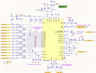
Here is our circuit. I have also attached an Excel sheet that captures our device configuration.
BQ76952 Protector Setting Configuration.xlsx

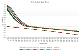
I tried to reproduce the issue by leaving a battery plugged in for 18 hours and logging the cell voltages using BQStudio. The board was not turned on (i.e., only the protector IC was powered), and I had purposely only discharged cell 6 to 4V. Below is the graph from the test.
Here are three key observations from the 18-hour test:

  1. While I was not able to reproduce the issue, I found that the IC was not able to balance the cells to a delta of 10mV even though Settings:Cell Balancing Config:Cell Balance Stop Delta (Relax) is set to 10mV.
  2. BQStudio reported that the IC was in sleep mode, so the current consumption should have been in the microamp range. However, I measured a 648mV drop across R14, indicating a current draw of 6.48mA.
  3. Even though cell 6 is not actively being discharged (i.e., the IC is not PWM-ing the internal discharge FET), I see a constant parasitic draw of about 0.04V / 20Ohms = 2mA. I measured this current by measuring the voltage drop across the 20-Ohm series resistor as well as by using a current probe on the sense wire from the battery pack. Both measurements agreed that there was indeed a constant 2mA draw out of the cell. This is also confirmed by the fact that cell 6's voltage decreases over time (as pictured in the above graph).

Please provide any insights that could help us identify the root cause of these battery failures.

Thanks,

Zaya

  • Hello Zaya,

    Thank you for sharing your schematic, configuration file, and observations. Please give me some time to review it. This previous forum may be helpful as well: BQ76952: Cell Balancing

    Best Regards,
    Alexis

  • Hello Zaya,

    I noticed on the schematic you don’t seem to have anything connected to the DSG pin. Is that intentional? Without a path to the DSG pin, there is no discharge protection. 

    Also, can you try using the subcommand, CB_ACTIVE_CELLS() and take a log of this to see if it’s actually attempting to balance? The batteries could be discharging faster than it can balance out. Table 10-1. Host-Controlled Cell Balancing Subcommands in the BQ76952 Technical Reference Manual can help with that.

    Another factor that can affect cell balancing is the temperature. If the temperature is above or below the Settings:Cell Balancing Config:Min Cell Temp/Settings:Cell Balancing Config:Max Cell Temp, the device will disable balancing as well. Do you know if the temperature is within the correct range?

    Best Regards,
    Alexis

  • Hi Alexis,

    Thank you for taking a look at this!

    We do not have anything connected to the DSG pin because our discharge protection is implemented somewhere else.

    I can confirm that the IC was attempting to balance the cells because I saw the PWM current for the cells using a current probe and oscilloscope. Below are example captures for cell 1.

    The first figure shows the PWM current from cell 1 when it is discharging. The second figure shows the return current through cell 1 when cell 2 is discharging. The IC alternates discharging even and odd cells. From my understanding of the IC, I do not see anything abnormal here. Can you confirm?

    I would like to reiterate that the cells were not discharging faster than the IC could balance them because there was no load during this test (i.e., we are in RELAX mode). The cells are decreasing in voltage because of the parasitic draw from being plugged into the board (with the board powered off). Only the protector IC is powered on (through the cell voltage sense wires).

    BQStudio reports reasonable temperatures for the IC and battery thermistors (32.8C and 28.7C, respectively). The unused thermistor inputs report -273.2C.

    Best,

    Zaya

  • Hello Zaya,

    Thank you for sharing those waveforms and checking the temperature. I understand that there was no load, however, the amount of parasitic draw from being plugged into the board is abnormally large. Can you change out the IC and see if that is still the case? 

    Also, the image you shared about the cells with regards to the 18 hr test with a load, already shows the other cells (other than Cell 6) not as balanced. From the configuration file, I see that you have it start balancing when the minimum voltage is above ~3.5V. We recommend starting balance a lot earlier so that the cells do not have such a large difference as it makes it more difficult to balance out, especially while there is a load. 

    Best Regards,
    Alexis

  • Hi Alexis,

    Thanks for the reply.

    I have conducted a similar experiment using the BQ76952EVM evaluation module. I found that the IC only draws 276uA while balancing the cells in Relax mode.

    I will get back to you once I find out why the IC draws so much more current in our design.

    Best,

    Zaya

  • Hello Zaya,

    Thanks for letting me know. 

    Best Regards,
    Alexis

  • Hello Alexis,

    I have not yet figured out why our design causes the IC to draw more current than expected, but I ran another test using the BQ76952EVM evaluation module. This test was intended to characterize the performance of the IC when a battery with a low state of charge is left plugged in for an extended period. Please review the graphs below.

    The red lines on the graphs indicate when the IC should stop balancing the cells (at 3.5V). I have a few questions based on the results of this testing:

    1. The delta begins to exceed the 20mV minimum delta setting before the cells reach 3.5V. Is this expected behavior?
    2. The cell voltages drop drastically, even though the IC current is in the hundreds of microamps range on the evaluation board. Why are the cells being discharged so quickly? Is it because the cells are near the "knee" of their discharge curves, meaning even a small current draw causes the cell voltages to drop rapidly? In these cases, does the IC not switch to a lower current mode in autonomous mode?

    Thank you again for all your help!

    Best,

    Zaya

  • Hello Zaya,

    Thank you for showing me those graphs.

    1. Based on your configuration file settings you shared; I would say this is expected. Your Cell Balance Min Delta is 20 mV. This means the max and min cell voltages must be greater than 20mV for automatic cell balancing to begin. This previous forum post, Cell Balancing, explains the specifics of how certain settings work. This Cell Balancing w/ BQ769x2 Battery Monitors application note may also be useful in explaining cell balancing for our device as well.

    2. It can heavily depend on the battery cells itself. Cells can have different capacity, state of charge, impedance, as well as different stress exposed during charge/discharge.

    Something else to note is that I believe you have Cell Balance Min Cell Voltage set to 3500mV. While not charging/discharging, automatic cell balancing will be disabled if the minimum cell voltage is less than that value.

    Our device has lower currents for modes other than Normal Mode. Section 13 Device Functional Modes in the BQ76952 Datasheet explain them briefly and the Section 7.5 Supply Current provides the different currents in those modes typically. Depending on your configuration, you could have the device 'switch' to a lower current mode, however, certain monitoring/protections will be given up in the process which may not be desired.

    Best Regards,
    Alexis