This thread has been locked.

If you have a related question, please click the "Ask a related question" button in the top right corner. The newly created question will be automatically linked to this question.

UCC28951-Q1: Excel sheet errors ucc28851

Part Number: UCC28951-Q1

Tool/software:

1. The delay resistor values calculated in excel sheet vary based on shim inductor value and transformer leakage inductance value. Which row is correct and where to fill data ?

2. In application notes , we have seen ( 2* Coss ) is calculated for tank frequency. Does excel also considers the same ? Or should we manually do ( 2* Coss )

3. Why 2* Coss should be considered if that's correct.

4. If shim inductor value is mounted more than desired , what can happen? And what we need to take care.

  • Hello,

    Your inquiry has been received and is under review.

    Regards,

  • Hello,

    1. The delay resistor values calculated in excel sheet vary based on shim inductor value and transformer leakage inductance value. Which row is correct and where to fill data ?

    > The excel tool was based on application note slua560d and was used to design a 600 W evaluation module.

    > This application note uses estimates of switch node capacitance based on Coss, leakage inductance and shim inductance to estimate the turn-on delays.  These turn-on delays will have to be fine tuned based on the designs actual switch node capacitance.

    > The cell equations should match what is presented in the application note.

    > These calculations are based on a fixed delay design approach and a rough approximation for switch node capacitance, which is 2* Coss.  The actual switch node capacitance is much more difficult to estimate, it is based on transformer turns ratio, output capacitance, PCB capacitance, transformer parasitic capacitance etc.

    > It is recommend that you use the excel tool for the initial delay timing calculations for turn-on delay and then fine tune the delay in circuit to  achieve ZVS and valley switching.

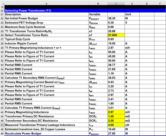
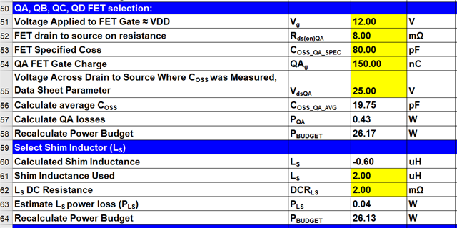
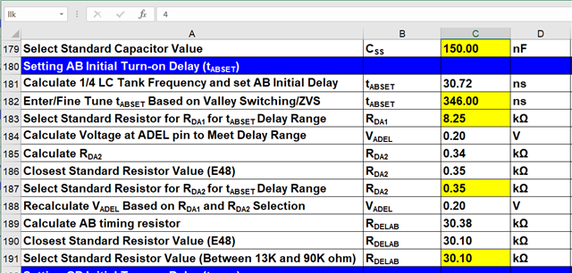
    >To get the estimated timing for turn-on delay for FETs QA..QD.   You need to correctly fill out the yellow highlighted cells below.

    If you have filled out the yellow cells out correctly to this point the initial delay timing for TABESET should be in the cell found in row 181, column C.  Please note this estimation is the same for TCBSET according to application note mentioned above.

    2. In application notes , we have seen ( 2* Coss ) is calculated for tank frequency. Does excel also considers the same ?

    > Yes

    Or should we manually do ( 2* Coss )

    > No

    3. Why 2* Coss should be considered if that's correct.

    > This is a rough estimate of switch node capacitance. Both FET Coss capacitances are consider to be in parallel at the switch node when it comes resonance.   It is just used to set initial delay timing which you have to fine tune once your circuit is built.

    > A better estimate of switch node capacitance would require to consider all parasitic capacitances of the PCB and transformer; as well as, reflected output capacitance across the transformer.  You would even have to reflect the parasitic capacitances on secondary across the transformer to the switch node. 

    > I do have another option for you if you need to know what the true switch node capacitance (Csw) of your design rather than estimating it.  Once your design is built used the measure the ring frequency (fr) of the switch node in your design and the following equation.  Enter fr, Llk and Ls in the following equation and solve for Csw.

    2*3.14*fr*(Llk+Ls) = 1/(2*3.14*fr*Csw) 

    4. If shim inductor value is mounted more than desired , what can happen? And what we need to take care.

    > The tool estimates sizing the shim inductor based on achieving ZVS at switch node QBd at 50 % load.

    > So if you use more shim inductance you should be able to achieve ZVS down to lighter loads.

    > If you use more shim inductance your actual tank frequency period will increase.

    There is another option for you and that is much easier method to set the turn on delays.

    1. Used a fixed delay approach.  Tie ADEL and ADELEF to ground.

    2. Use a 100 k potentiometer for resistors RDELAB and RDELCB and set the initial resistances to these pins 100 K ohms.

    3. Load the circuit to 10% load and adjust the delay timing to 1/4 the resonant tank frequency.  You should be able to get the exact timing by adjusting the potentiometer impendence.

    4. If you did this correctly you will have ZVS and at lighter loads valley switching.  The FETs should turn on at 1/4 the resonant tank frequency at the switch node.

    Thank you for interest in Texas Instruments (TI) products.  If you have a related question, please click the "Ask a related question" button in the top right corner. The newly created question will be automatically linked to this question.

    Regards,