Tool/software:
I am working with the UCC28C56L-Q1 flyback controller for a power supply design and have encountered a couple of issues regarding the startup and operational mode.
1. CCM vs DCM Operation:
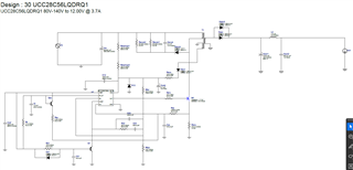
I used the Webench tool to design a PSR-based flyback converter with an input voltage range of 80V to 140V and a 12V 40W output. The Webench design example uses Continous Conduction Mode (DCM), but I need to know whether the UCC28C56L-Q1 is designed to operate in Continuous Conduction Mode (CCM) as well as it optimized for DCM as suggested in the datasheet example?
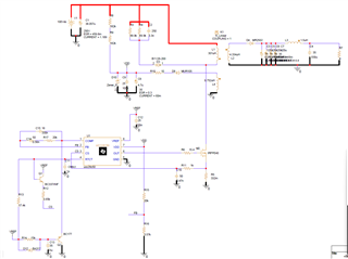
2. PSR Startup and VDD Voltage:
When I tried simulating the exact design in PSpice, I noticed that during startup, the VDD pin of the IC is only receiving 7V instead of the expected 22V. I traced the issue to the voltage drop across the resistors Rfbt and Rfbb. This voltage drop prevents the IC from turning on, which results in no output voltage. Could you provide some insights into the possible causes for this issue and how to prevent the VDD voltage from dropping too low? Are there any recommended resistor values or guidelines for setting the feedback resistors to ensure proper startup behavior?
3. Minimum Duty Cycle Assumption for Transformer Design:
While calculating the transformer design using the values provided in the datasheet, I wanted to clarify on what basis the minimum duty cycle is assumed as 0.8 for these calculations. Is there a specific guideline or condition (such as the minimum load or operating conditions) under which this minimum duty cycle is derived?