Because of the holidays, TI E2E™ design support forum responses will be delayed from Dec. 25 through Jan. 2. Thank you for your patience.

This thread has been locked.

If you have a related question, please click the "Ask a related question" button in the top right corner. The newly created question will be automatically linked to this question.

BQ76952: BQ76952

Part Number: BQ76952
Other Parts Discussed in Thread: SEGGER

Tool/software:

Hi Team,

We are using BQ76952 IC with STM32L452 microcontroller.

Do we have any connection sequence for the cell voltages from C0 to C16 and powering the IC to VBAT to be followed while powering up the BMS board.

Here is the failures inspected:

We are following a connection sequence.

1. Connecting the overall positive to the BMS as the GND is common for all.

2. Connecting the C0-C7 first at a same time.

3. Connecting the C8-C16 second at the same time.

4. Flashing the micro with the segger JLINK.

Sometimes following this we have observed the Micro is unable to read the device ID of AFE over I2C communication lines, which we used as a first step in order to go ahead in next set of line code.

We have observed the REG1.8 is nearby 0.4V, 0.3V, 0.9V, 1.3V it means the AFE is not working.

I have replaced the AFE and it starts working. 

  • Hello Varij,

    Our part supports random cell connection with some restrictions. This Connecting Battery Cells to the BQ769x2 Family FAQ should be a useful guide. 

    Best Regards,
    Alexis

  • Hi Alexis,

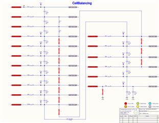
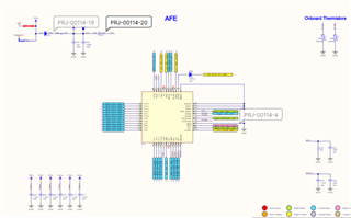
    Please find the attached schematics of our design for AFE and cell balancing . We are going for 14S configuration. We are following we are connecting at the certain VCx where it is recommended. Please have a look once again the sequencing what we are doing.

    The above sequence in the first thread is used is done in 4 boards and the REG1.8 values are stated above.

    Thanks and regards,

    Varij Prajapati

  • Hello Varij,

    Can you send the attached schematics again? The pictures are blurry for me. 

    Best Regards,
    Alexis

  • Hi Alexis please find the attached pdf , here apart from R73 & R75 resistance. All 0-ohm resistances are not populated in order to make the 14S configuration.
    AFE and cell balancing.pdf

    Let me know if you need any further information

  • Hello Varij,

    Thanks for sharing the pdf. You should remove R72, C74, R74, and C75 for the 14S configuration. Everything else looks good from the pdf.

    Best Regards,
    Alexis

  • Hi Alexis,

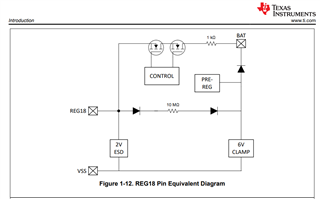
    Without removing this, will it create any impact can you please elaborate by taking one case scenario. & I am attaching hereby the image of pin equivalent diagrams for the REG18 pin, unable to understand how with the BAT voltage AFE is able to drop down it to 1.8V.

    Most of the baords wehre REG1.8V generation is not there i have witnessed that these REG18 pin is actually shorted to GND and along with that in 2 3 baords i witnessed that SRP and SRN pins are at very low resistance of 100 ohms nearby.

    Thanks and regards

    Varij prajapati

  • Hello Varij,

    You can keep the resistors and capacitors if you’d like, however, it’d be unnecessary is all.

    There is a preregulator that provides the regulated 1.8V for REG18. The pin equivalent shows a simplified version of the internal circuit there. Nothing further is shown in the pin equivalent diagram as it is proprietary information.

    Best Regards,
    Alexis

  • Hi Alexis,

    Thanks for the information. Can you please help if you see in schematics the Cell0 connection i.e VC0 is connected with a filter capacitance in order to keep the grounds common. Do we need to populate the R79, you will see in the cell balancing section at the VC0 point.

    Thanks and regards,

    Varij prajapati

  • Hello Varij,

    Did you mean R97? If so, yes you would want R97 re-populated. I mistakenly thought you meant only the 0-ohm resistors between the cell connections were not populated except for R73 and R75.

    As stated in Section 16.3 Random Cell Connection Support in the BQ76952 Datasheet, the VC0 has a lower voltage tolerance compared to the other pins and is therefore expected to remain close to the VSS pin during cell attach. 

    Best Regards,
    Alexis

  • Hi Alexis,

    Thanks for the key information.  

    Hereby I am explaining my setup what I have made in order to power up the board and how we are giving the cell inputs.

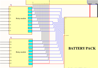
    We are controlling the VC0- VC14 (I will say as we have developed for 14S configuration) with the help of mechanical relays.

    1. VC0-VC7 connections are provided to one relay module and we are operating all relay at once.

    2. VC8-VC14 connections + separate power i.e. VBAT to AFE is still from Cell14(top stack) but the nets are different in PCB.

    We are turning on the first relay module first(VC0-VC7) and then after delay of 2secs we are operating the relay VC8-V14.

    In the same sequence we, have witness the AFE REG1.8 is getting damaged and shorting to GND.

    Here is the snippet attatched of the SLD.

    Let me know if you need any additional info.

    Thanks and Regards

    Varij prajapati

  • Hello Varij,

    Was that result with R97 re-populated?

    Best Regards,
    Alexis

  • Hi Alexis,

    No the result was without R97 populated.

    But we have performed the same with R97 populated we are facing the same issue, but the frequency reduces.

    & Can we have a team's call to explain you what we are doing how many types of failures we have seen, then we can find the solution.

    Thanks and Regards,

    Varij Prajapati

  • Hello Varij,

    Just to double check, when you say the REG18 pin is “shorted” to GND, the part is not in SHUTDOWN mode correct?

    Also, when REG18 is damaged, is there any safety alerts/faults that are occurring too?

    Do you also have any waveforms of the voltage/current into the part once the cells are connected in the procedure you mentioned to share?

    Best Regards,
    Alexis

  • Hello Viraj,

    From my experience, I suggest following this sequence just to test the system:

    1. Remove Cell 1 Negative from your relay setup and ensure that is connected first before any other connections.
    2. Connect BAT- (your high current negative line from your battery)
    3. Turn on the lower relay (VC1-VC7) as you normally do.
    4. Turn the next set of relays after your 2sec relay as your normally do.

    Can you see if this sequence helps? If it does not and if you have not already tried, then you may want to check if the mechanical relays are causing the problem. You may try using a normal connector to connect the cell taps to your PCB completely omitting the relay.

    I say this because, as you may know, mechanical relays are infamous for bouncing before it settles and a solid contact is made and since VC16 is the same line that is used for REG18, this transients maybe causing some unexpected issues for the silicon. I have had a similar issue before.

    Like  asked, it maybe helpful to see some waveforms of these lines.

  • Hello, Abhijith,

    Thanks for providing the key information. We have done the same almost. I have done the things as mentioned below and it worked.

    1. I have connected the VC0 connection permanently as it will serve as the GND/VSS for the complete system.

    2. I have turned on the relays for VC1-VC7 and then after delay of 5 sec turned on the relay with VC9-VC14.

    3. In order to power the AFE and other subsystems which we consider it as BMS PWR that I have split from top stack of cell and was switching along with C14. We have faced a lot of failure in AFE, and all the time failures was different like AFE RE1.8 shorting, voltage fluctuations in adjacent cells.

    Now I am only switching the cell 14 and in order to power the subsystem, I split it after the relay switching. Now it worked for me.

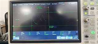
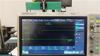
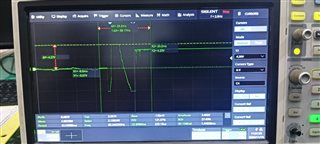
    I am attaching the images of the waveform that I captured. These are between VC0-VC1 & VC2-VC2

  • Hello Abhijith and Alexis. 

    Thanks a lot for helping me out during these times. Finally, my issue has been solved. 

    But still, I am clueless about what is the exact root cause. I will be very happy to discuss with you both in a team's call collectively if possible and convenient to you both to understand more about the AFE and its behaviour for future reference.

    I will take the initiation to schedule the call.

    Thanks and regards

    Varij Prajapati

  • Hello Varij,

    Thank you for sharing your waveforms. I’m glad Abhijith's suggestions helped you regarding your issue.

    From the waveforms you shared, while I’m not sure which waveform is of which cell connections, one of them shows the voltage going negative seemingly below our minimum cell input voltage specs. Section 7.1 Absolute Maximum Ratings (continued) in the BQ76952 Datasheet shows this information. This could be a cause for why the part was being damaged.

    Best Regards,
    Alexis