UCC25660: LCC Primary-Side MOS

Part Number: UCC25660
Other Parts Discussed in Thread: UCC28180, UCC24624, UCC25600,

Tool/software:

HI ALL

We are currently designing a 1000W AC/DC system using a PFC UCC28180 + LLC UCC256604 without HV startup + SR UCC24624 configuration.

The design specification for Vout is 40V/25A.

We have identified an issue where, under loads exceeding 320W, the temperature of the Primary-Side MOS increases abnormally fast. Within approximately one minute, its surface temperature can reach 100°C.

If this condition persists for a period of time, the temperature can exceed 180°C, resulting in burnout.
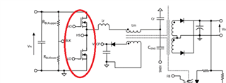
I suspect that it might be caused by a shoot-through short circuit in the half-bridge circuit, but I am unsure how to address it.

1.Replace with a faster FRFET MOSFET? Which parameters should we focus on? Ciss, Coss, or td(on), td(off)?

2.Modify the design to make the LLC Gain Curve flatter (with a higher QE value?ZCS?ZVS?).Attach the design table.UCC25660x_Design_Calculator_Rev1.8_Noah.xlsx
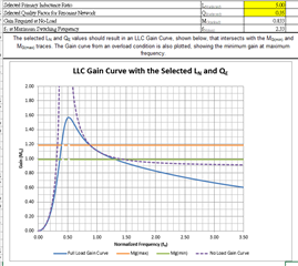
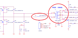
3.Under the existing design architecture (without modifying the transformer), adjusting Ln and QE while keeping the LM value fixed means only the LR value can be adjusted. Can the LR value be equivalently represented as LLK (leakage inductance) + LR (external inductance)? I am unsure if my interpretation is correct.

EX: LP=L2+  LLK (leakage inductance) = 10 + 12= 22 uH .Attached is the circuit diagram.sch_adp1000a_e20_20241118.pdf
Thanks

Regards

  • Hi Noah,

    For 1000W design, I would go with Mosfets with TO247 or TO 220 packages with heat sinks. That should help reduce the temperature rise of the FETs.

    For your design, use the Discrete inductor option in the calculator. And add the external inductance value plus transformer leakage value in the place of leakage inductance. Having Lm/Lr from 3 to 5 should help achieving the ZVS. I dont see any issue with the current gain curve that you shared. 

    Let me know if you have any further questions.

    Regards

    Manikanta P

  • Hi Manikanta 

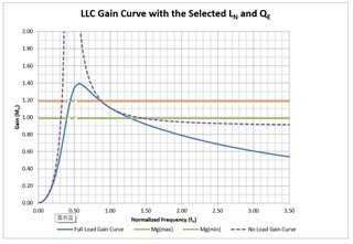
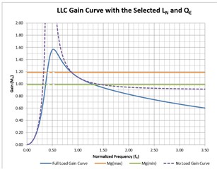
    I have a question regarding the following graph, which shows curves derived from two different QE values. In terms of LLC design, is it better to have a higher or lower QE value? (Should the curve be steeper or gentler?)

    For the UCC25600, does ISNS provide protection for the ZCS region? If RISNS is adjusted, will it affect the protection of the ZCS region? For example, mistakenly entering the dead zone.

  • Hi Noah,

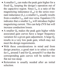
    Please refer the attached app note for recommended Ln,Qe values.

    Designing an LLC Resonant Half-Bridge Power Converter Article

    For the UCC25600, does ISNS provide protection for the ZCS region? If RISNS is adjusted, will it affect the protection of the ZCS region? For example, mistakenly entering the dead zone.

    Could you confirm which controller you are asking for? UCC25660 or UCC25600?

    Regards

    Manikanta P

  • Hi Manikanta

    Sorry, I meant UCC25660.

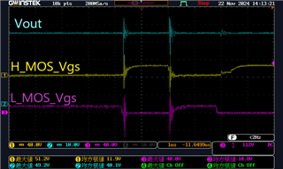
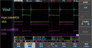
    Additionally, we measured the waveforms of Q7 and Q9 (High/Low side MOSFETs) including HO, LO, H_VGS, L_VGS, H_VDS, and L_VDS, as shown in the attached diagram.

    Based on the waveform, is it abnormal or has it already entered the dead zone?

    Do you have any suggestions for improvement?

    Thanks

    Regards

    Noah

  • Hi Noah,

    In UCC25660x, ISNS pin does provide protection against entering into the ZCS region. Making RISNS too low, will make the ISNS magnitude too low and might trigger ZCS.

    In one of your waveforms, looks like controller is operating in HF Burst. What's the issue that you are facing other than MOSFET heating? 

    Regards

    Manikanta P