Tool/software:
Ecco la mail aggiornata con la frase aggiuntiva:
Hello everyone,
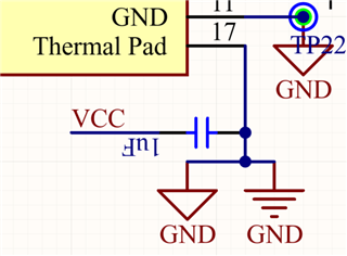
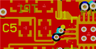
I am designing a solar battery charging system using the BQ24650 chip, but I am encountering some issues. Attached you will find the schematic I created, following the BQ24650EVM-639 guide. The only differences I made are to the following components:
- R13 = 300k
- R19 = 68k
This is because I want to charge a two-cell lithium battery (so the maximum charging voltage should be 8.4V) and I am using two photovoltaic cells in series, with a Vpp of 10V (each cell has a Vpp of 5V) and an Ipp of 36.6 mA. The panels are small due to space constraints.
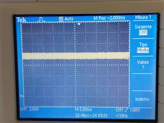
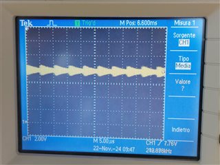
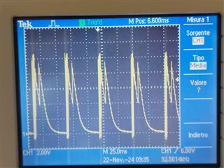
I tested the board I made based on this schematic with both the solar panel and a bench power supply set to 10V, and the current draw is 2 mA. The STAT1 LED is on, indicating that charging has started, and the VFB voltage is 1.75V instead of 2.1V. Obviously, the charging does not start, even though my battery is at 7V. When the battery is disconnected, VFB is zero, and strangely, the STAT1 LED remains on.
I do not notice any difference whether I enable or disable the charge enable, and currently, I am using a 10k resistor instead of a thermistor because I am not interested in this functionality.
How can I resolve these issues? I look forward to your kind response.
Best regards,
Costanza


