Because of the holidays, TI E2E™ design support forum responses will be delayed from Dec. 25 through Jan. 2. Thank you for your patience.

UCC28750EVM-071: UCC28750EVM-071 problems

Part Number: UCC28750EVM-071
Other Parts Discussed in Thread: TPS25740A, UCC28782, UCC28750

Tool/software:

hi team

I'm working on flyback converter with PD,and made pcb assembly.
1、After the sample is connected to AC110V, PD does not work.
2、than disconnect the PD block ,I found output voltage of flyback converter is unstable. (a normal output is 5VDC)
3、Even if the resistance of FB is changed, the situation is the same.
4、flyback converter circuit is designed with reference to UCC28750EVM-071, and the PD circuit is designed with reference to TPS25740A specifications.

The schematic is as follows:

sch_ucc28750power.pdf
Please help confirm whether errors in the schematic
many thanks!

  • Hello,

    What is your input and output power requirement?

    Does it have the same power requirement as the UCC28750EVM-071?

    Regards,

  • hi mike

    The power requirements are the same as the UCC28750EVM-071,
    only output voltage is changed from 24V to 5V.

    Many thanks

  • Hello,

    That is a large change in the design.  I did review your schematic and functionally it seems correct. 

    The first thing I would recommend is that you check the components selected  with the excel design tool that can be found at the following link.

    https://www.ti.com/tool/download/UCC28750-CALC

    Things that could be causing your design not to work could be any of the following.

    1. Transformer turns ratios are incorrect

    2. Output capacitor bank is too small for the design

    Regards, 

  • hi mike

    thank you for your suggestion, and I'll try to check these points.

  • hello mike
    my design is totally reference to UCC28750EVM-071,so i use values of UCC28750EVM-071 to fill in UCC28750-calculator tools,but some of items are not really sure.
    so please help to check if the value of user input correct or not.
    attachment below for details and Feel free to give your comments.
    many thanks!
    fill in UCC28750 calculator_20241128.pptx

  • Yang-lun,

    Please give us few days to get back to you.

  • Hello,

    I reviewed your PPT, added comments and attached for your reference.  However, I think your main issue is that your transformer turns ratio is not correct.  This will cause the output and VDD of the controller not to be regulated correctly. This is most likely why your design it not working correctly.

    If you want to modify the EVM based for your design requirements, since it is the same power level, you should do the following.

    1. Set the Np/Ns transformer turns ratio to 27

    2. Set the Na/Ns = Vaux/Vout = 12V/5V = 2.4

    3. The primary magnetizing inductance of the transformer should be the same as the EVM, if you are basing your design on the EVM.

    4. The output capacitance need to increase by Cout*24/5 = 4.8 and total ESR needs to decrease by 4.8.

    5. The output capacitance bank ESR needs to be decreased by a factor of 4.8

    6. The output capacitor bank current ratings need to be increase by a factor of 4.8

    7. You will need to resize R19 to maintain your lower output voltage.

    8. You will need to recheck your design with a network analyzer.

    fill in UCC28750 calculator_20241128 12 4 22.pptx

    Regards,

  • hi mike 


    I'm trying to adjust the output voltage from 5V to 24V
    Make the following corrections:
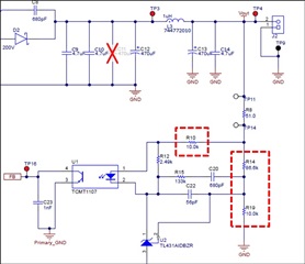
    Change R14 to 86.6k
    R19 changed to 10k
    R10 (optocoupler current limiting resistor) is changed to 768R


    After testing, the output voltage is stable at 24V, but it is incompatible with the voltage selection programming resistor of the PD module.


    1、Could it be that the design of this EVK cannot adjust the output voltage arbitrarily?
    2、If the output voltage is adjusted, does it mean that the turns ratio of the transformer also needs to be adjusted at the same time, otherwise the operation will be abnormal?

    Regards

  • Hello,

    A 5 to 1 change on the output voltate is quite large.  This will be a 5 to 1 change in duty cycle.  I looked at the EVM and it looks like the maximum duty cycle at 85V AC is around 50%.  So when you drop the output votlage to 5 V the duty cycle would drop down to 10% at full load. Most CCM converter can only only control the duty cycle down to 1 to 2%.  So you may have isssues congtrolling the duty cycle below 20% load.

    I reviewed the UCC28750EVM-071 and it looks like it was designed for critical conduction.  If you want to use this design at 5 V the transformer will not be able to deliver full load power at 10% duty cycle.  So you are correct that the large variaion in the output voltage is not achievable with this design.

    I found a 60 W reference design using the UCC28782 active clamp flyback where the output was designed for 5, 9, 15 and 20 V selectable.  This is for USB C designs.  If you do not have to oppearte at 24 V output, this could be an option for you.  The following link will get you to the reference design.

    https://www.ti.com/tool/PMP22244

    If you decide that you want to design an active clamp flyback and have questions regarding the UCC28782 and how to design with it.  Please repost in the e2e with the UCC28782 in the title so we can have apropriate applications engineer handle your inquiry.

    Regards,

  • hi Mike


    I think I've found the reason why the paradigm I designed doesn't work.
    the system can output a normal 24V now.
    and I'm working a load testing ,but when output exceeds over 24W, the system shutdowns.
    here is voltage on each pin in UCC28750 (Measure with Multimeter):


    are these value in table normal?
    please help.


    Regards

  • Hello,

    Your VDD voltage is not normal.  If you output is regulated at 24 V your VDD should be well regulated.  I looked at your schematic and you have a 20 V Zener across the VDD pin.  So it should not be increasing to 27.2 V.  This is one issue you need to resolve.

    So if the output is shuting down it is due to a fault most likely.  My guess is over power protection.  I would double check your current sense resistor to make sure it was properly selected.

    Regards,

  • hi

    I tried load testing on another sample ( sample 2) and when the power increased over 33W, the system shutdown.
    This is the voltage at each pin in the UCC28750 (measured with a multimeter):


    And I found that VDD seems to stay around 20V,it won't increase anymore.
    information above is also provided for your reference. I hope it will be helpful in finding the problem.
    many thanks.

  • Hello,

    So the VDD voltage is not your issue. 

    So more than likely the design is shutting down due to a fault.  Study the FB, CS, FLT, Vout with an oscillascope.  Trigger on when the output drops out and look at the last three switching cycles.  This will point you in the direction to which fault is causing the shut down.

    My thought is that this could be an over power protection (OPP) fault, this is where the FB pin is greater than 2.6 V (VOPP) for 85 ms (tOPP).  If this is the case more than likely your current sense is too large or you adding too much slope compensation.

    If you verify that the issue more than liklely your CS resistor is too large and should be decreased.


    Your current resistor (RCS) should be based on 80% of the maximum current sense signal (VCSmax) and the nominal peak current (IPK) at maximum load.

    RCS =  VCSmax*0.8/IPK=900mV*0.8/IPK

    The slope compensation needs to be set to half the inductor down slope.  For most application if you add 200 mV this will work.

    Regards

  • hello

    it's my modification:
    R13(slope):1K->430R
    R16 and R17(RCS):287.5mR->179.5mR
    after tesing ,the sample can output 24V/60W steady,but some parts make high-frequency noises,except that,everything works fine.
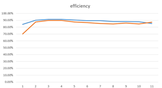
    here is the efficiency Test:

    Regards