


Tool/software:
Hello,
i'm facing a problem using the UCC21750 +UCC15241 in a 2L 3-Phase Inverter (25kVA) using SIC devices PN:C3M0040120K (2 in parallel).
Some important information about the project:
- Output power = 25kVA.
- Output Inductor =196uH.
- Output Voltage = 220-240V (Phase to neutral).
- Switching frequency: 45kHZ.
- DC-BUS VOLTAGE = 830V.
- VDD-COM = 15V.
- VEE-COM = -4V.
- VCC-GND = 5V.
About the issue:
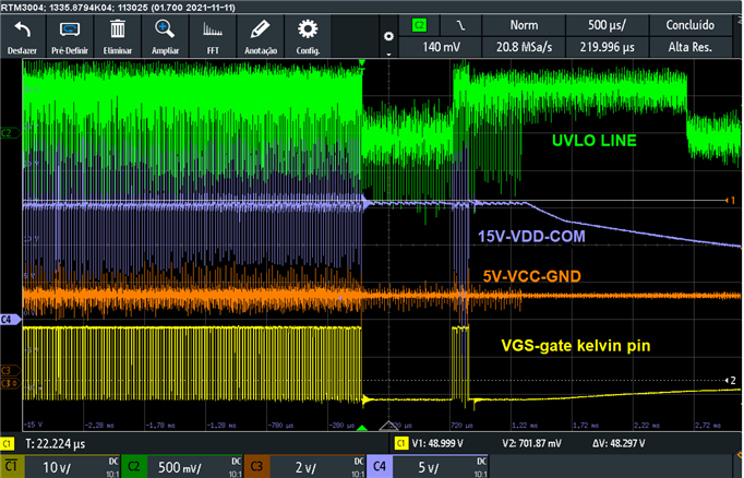
When the converter is operation in nominal load or more than 80%, sometimes the RDY(UVLO) signal is trigger, but it seems to be no issue in the supply voltage levels.
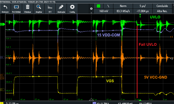
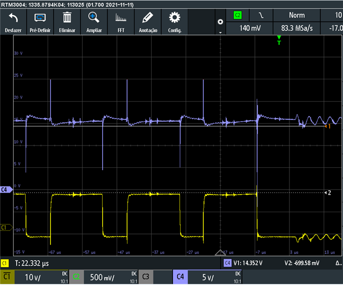
In the waveformas below, it is possible to observer, that the UVLO line is pulled down (green) and the switch command stop to work at the same time (yellow).
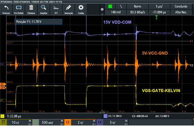
In blue and red, is possible to observer the VDD (15V) and the VCC (5V) voltages, that seems to be fine.
This problem only happens, when the deadtime is less than 400ns. With a deadtime of 400ns, this problem is not observed.
It seems to be a noise issue, but i want to know, if there is someone that already face some similar problem.
thank you,
