BQ25756E: Can't reliably "wake up" a battery whose BMS has disabled its output due to overdischarge

Part Number: BQ25756E
Other Parts Discussed in Thread: BQ78350-R1, BQSTUDIO, , BQ25756

Tool/software:

I'm going to have several questions here related to my design (each question in bold).

I've designed a battery charger using the BQ25756E, and it is charging an 8-cell, "24V" LiFePO4 battery pack at 2.96A ICHG and 29.14V VCHG nominally.  Its VAC is provided by a 24V benchtop power supply for testing (will eventually be an AC/DC supply in the product).

This battery pack has a BMS (BQ78350-R1) in it that disables the battery's output once the battery gets discharged below a certain level: 20V in my case.

My problem is that the BQ25756E is unable to (reliably) "wake up" this battery to begin charging it.  However, simply applying an external power supply voltage works just fine (and the battery "wakes up" immediately upon voltage application).  Also once the battery is "awake", the BQ25756E works just fine as far as I can tell.

In order to "wake up" the battery, it seems I need to apply a certain voltage (something above the battery's internal voltage, I assume).  I also assume perhaps there needs to be a certain minimum charging current associated with this.

  • Can you help point me to the right place in the BQ78350-R1 datasheet that talks about how to "wake up" a battery that's been overdischarged to its CUV limit? I am struggling to find this in its datasheet.

Some o-scope screenshots:

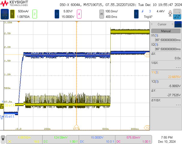
Sometimes the BQ25756E wakes up the battery just fine (Blue = output voltage of BQ25756E, yellow = output current into battery; the battery is "awakened" once the charger starts charging at the ~3A rate):
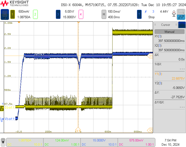
Sometimes it works, but with what looks like a retry:
Sometimes it doesn't work at all:
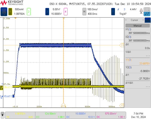
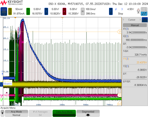
With no battery attached, the o-scope shot looks like the 3rd plot above (except the output voltage gets up to the VCHG value of ~29V).  My understanding was that the BQ25756E was supposed to retry once the output bled down to the VRECHG value (97.5% of VCHG by default).  This clearly is not happening.

  • The current "fuzz" between ~200ms and 600ms are quick pulses of ~300mA at varying / inconsistent times.  Any idea what that is?
  • The larger spikes after ~600ms occur at a consistent ~13ms period.  Any idea what this is?
  • What is the trickle charge current value?  I can't find it anywhere...

FYI - I have not yet hooked up to bqstudio so far, but plan to if i can't get any farther.

Thanks for the help!

-Bill

  • Hello Bill,

    Thanks for working on this.

    Can you help point me to the right place in the BQ78350-R1 datasheet that talks about how to "wake up" a battery that's been overdischarged to its CUV limit? I am struggling to find this in its datasheet

    The IC should do this by entering into trickle charge and bringing up the battery voltage.

    The current "fuzz" between ~200ms and 600ms are quick pulses of ~300mA at varying / inconsistent times.  Any idea what that is?

    This might be the inductor detection running. I would need to see the SW1 and SW2 waveforms to be sure.

    The larger spikes after ~600ms occur at a consistent ~13ms period.  Any idea what this is?

    I'm looking into this. The VBAT voltage shouldn't fall if there's no battery connected.

    What is the trickle charge current value?  I can't find it anywhere...

    The trickle charge is ≈150mA.

    I have a few questions to help troubleshoot this:

    • Are all of these tests done with the same IC?
    • Is there any difference in the tests where the output voltage comes up and when it doesn't?
    • Can you send me your schematic so I can review it?

    Best Regards,
    Ethan Galloway

  • Can you help point me to the right place in the BQ78350-R1 datasheet that talks about how to "wake up" a battery that's been overdischarged to its CUV limit? I am struggling to find this in its datasheet

    The IC should do this by entering into trickle charge and bringing up the battery voltage.

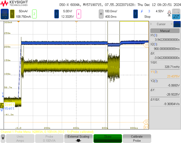
    This is what's so weird and makes me think there is also a certain minimum current that should wake up the battery.  The charger output voltage on all 3 plots are very close to the battery voltage, it sometimes wakes it up and sometimes doesn't.  I tried the BQ25756EEVM, and the current waveform is different.  There is just a solid, consistent ~150mA (see below) rather than the fuzzy/choppy bursts of ~300mA on my circuit.  For ~600ms it's in what i assume is trickle charge.  Then another ~100ms it's potentially in another mode, then it delivers the full charge current.  Any ideas why my charger doesn't show this nice, consistent 100mA trickle current?

    The current "fuzz" between ~200ms and 600ms are quick pulses of ~300mA at varying / inconsistent times.  Any idea what that is?

    This might be the inductor detection running. I would need to see the SW1 and SW2 waveforms to be sure.

    I'm not sure exactly what you want to see and where.  But I can see that in the small ~300mA current pulses, it is in DCM.  This scope doesn't have enough sample depth to be able to capture the whole ~1s worth of data at a resolution high enough to see the SW node waveforms.

    If you can tell me what this inductor detection looks like, I can look out for it.

    I have a few questions to help troubleshoot this:

    • Are all of these tests done with the same IC?
    • Is there any difference in the tests where the output voltage comes up and when it doesn't?
    • Can you send me your schematic so I can review it?
    • Yes, all the same IC on the same PCBA.
    • No difference in the test setup (same battery, same wiring, same power supplies, etc).
    • I can send you schematics, but not over the public forums.  Can you provide your email address, or send me an email?

    There is 1 curious difference I see in the BQ25756EEVM that isn't mentioned in the datasheet and therefore wasn't done on our schematic:  There is some compensation on the ICHG pin (R201 and C201).

    The VBAT voltage shouldn't fall if there's no battery connected.

    That's what I'd expect!  And with no battery, the EVM's output voltage stays high (retrying after the voltage drops below Vrechg).  However, with no battery, our circuit's output voltage falls almost immediately.  This behavior is 100% consistent as far as I can tell (see below):

    -Bill

  • Hello Bill,

    Any ideas why my charger doesn't show this nice, consistent 100mA trickle current?

    Maybe the IC has gone bad? If you have the means, can you replace the IC on your board with the IC from the BQ25756E EVM?

    For the inductor detection, we have a brief description of how this works on the BQ2575X family FAQ.

    I can send you schematics, but not over the public forums.  Can you provide your email address, or send me an email?

    I sent you a friend request over E2E. Can you send me the schematics over the direct messages? You don't need to send the whole schematic. I just need to see the circuitry for the BQ25756.

    There is 1 curious difference I see in the BQ25756EEVM that isn't mentioned in the datasheet and therefore wasn't done on our schematic:  There is some compensation on the ICHG pin (R201 and C201).

    We recommend compensation when the ICHG resistor or the ILIM_HIZ resistor are greater than 5kΩ.

    This is pretty strange behavior.

    I have a few test suggestions:

    • Can you measure the voltage on REGN and DRV_SUP?
    • Does the behavior change if you set the bit EN_PRECHG=0?

    Best Regards,
    Ethan Galloway

  • Maybe the IC has gone bad? If you have the means, can you replace the IC on your board with the IC from the BQ25756E EVM?

    One thing we realized was that our feed-forward cap on the FB resistors was accidentally way too high at 0.1uF.  It was likely intended to be a dummy value that should have been unpopulated.  We removed this cap and things got a LOT better.  This alone almost solved everything for us.  The remaining behavior seems to be when our processor is booting up, it is accidentally disabling the charger.

    I sent you a friend request over E2E. Can you send me the schematics over the direct messages? You don't need to send the whole schematic. I just need to see the circuitry for the BQ25756.

    Yes, I can do that.  Even though we just about have things working now, I would really appreciate you looking over the schematic for the next spin of these boards.

    We recommend compensation when the ICHG resistor or the ILIM_HIZ resistor are greater than 5kΩ.

    Do you have any guidance / calculations / worksheets on how to choose this compensation? Our ICHG resistor is 16.9k (~3A) and ILIM is 4.12k (~5A).

    Thanks!

    -Bill

  • Along with guidance for the compensation, we also are seeing that the charger is not actually outputting the current it's set for - it's always a little lower (instead of 2.95A, we've seen ~2.6A and ~2.7A).  The voltage on Ichg looks fine and clean, but the differential voltage across SR_P and SR_N looks fairly noisy (compared to the EVM).  Is it reasonable to think that common-mode noise on the output sense line would affect the output current in this way?

  • Hello Bill,

    Thanks for the new information. I'm glad to hear the charger behavior is a lot better.

    Do you have any guidance / calculations / worksheets on how to choose this compensation?

    I recommend using an R value of 1.5kΩ and a C value of 100nF

    I'm looking at your schematic and I have a few suggestions:

    • The capacitance across the input sense resistor (R5) will need to be balanced. To quickly test this, you can install a 100µF cap in parallel with C10. We have an FAQ on the input and output caps. Here's the general FAQ just for reference.
    • I'd recommend shorting the switching FET gate resistors just for initial testing.
    • Make sure VAC has a capacitor close by to the pin.
    Is it reasonable to think that common-mode noise on the output sense line would affect the output current in this way?

    I think so. This common mode noise may be improved by the schematic suggestions above, though.

    Let me know if you have any questions about this.

    Best Regards,
    Ethan Galloway

  • I recommend using an R value of 1.5kΩ and a C value of 100nF

    Noted, thanks!

    The capacitance across the input sense resistor (R5) will need to be balanced. To quickly test this, you can install a 100µF cap in parallel with C10.

    This actually is (sort of) balanced.  On the first page I sent, there's an input filter with a 100uF capacitor (and 1-ohm series R):

    It isn't exactly the same, but we thought it would be good enough to "count" as balanced" as we are very tight on space on this design and don't have room for more big electrolytics.  Do you agree?

    I'd recommend shorting the switching FET gate resistors just for initial testing.

    The switching waveforms on these things is gorgeous, and I'm afraid to touch it Slight smile  We probably do have room to drive a little stronger, but I'm very happy with the measured efficiency (>95%).

    Make sure VAC has a capacitor close by to the pin.

    Already done!

    I'll take a look through all the other suggestions from your link, too - thanks!

    This common mode noise may be improved by the schematic suggestions above, though.

    I realized that our sense lines (both input and output) go right under all the switching stuff (buried between GND planes, so it could be worse).  However, the filtering components are at the sense resistor instead of the IC. I moved the capacitors (0.47uF differential and 100nF common mode) to the IC, and it reduced the noise a lotFor our next spin, would you also recommend moving the 10-ohm series resistors on the sense lines close to the IC, as well?

    Thanks!

    -Bill

  • Hello Bill,

    Thanks for being patient with this this. We are pretty busy at the moment. I'll get back to you on this later this week.

    Best Regards,
    Ethan Galloway

  • Hello Bill,

    This actually is (sort of) balanced.  On the first page I sent, there's an input filter with a 100uF capacitor (and 1-ohm series R):

    Yes, this should work. If possible for the circuit, I'd recommend shorting R57.

    We probably do have room to drive a little stronger, but I'm very happy with the measured efficiency (>95%).

    Thanks! If you run into any more issues with the charger starting up in the future, I would recommend shorting these resistors.

    For our next spin, would you also recommend moving the 10-ohm series resistors on the sense lines close to the IC, as well?

    Thanks for catching this. Yes, I would recommend moving the 10Ω resistors and filter capacitors closer to the IC.

    Best Regards,
    Ethan Galloway