A related question is a question created from another question. When the related question is created, it will be automatically linked to the original question.
If you have a related question, please click the "Ask a related question" button in the top right corner. The newly created question will be automatically linked to this question.
TPS28225: Can TPS28225 be used to drive latching relays
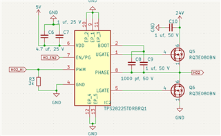
I need some more information to comment and give advice on the TPS28225 for this function. Do you have a schematic, even a simplified schematic of the circuit and the functions you need from the driver. Ex control inputs, outputs needed from driver, floating high side and low side, and also the operating voltage levels?
I plan to use two TPS28225 to open and close latching relay. I plan to send signal to PWM input to open highside mosfet and to other TPS to open lowside mosfet and open relay when i need it. And reverse logic to close relay.
Can TPS open and close mosfets when it gets only one pulse of control signal?
Can you confirm a couple of things. The TPS28225 is a single PWM input driver where the high side Mosfet is turn on when PWM is high and the low side Mosfet is turn off when PWM is low. Will this complementary operation work for driving the relay?
Also with a bootstrap bias for the high side Mosfet, boot to phase bias, the bootstrap capacitor is charged when Phase switches to ground. The bootstrap bias is not suited for high side Mosfet DC on operation or very long UGATE pulse widths. How long is the pulse width needed for the high side Mosfet to operate the relay?
Thanks for confirming the driver operation will work in the application. With long ugate on pulses you need to consider the value of the boot capacitor which will discharge during the Ugate on time. To determine the voltage drop from the quiescent current I am assuming the boot quiescent current is 1/2 of the total IDD current which includes the boot current, which would be 250uA. using C=Idt/dV for a 1 V drop at 20ms, C=5uF which is a large boot cap. in this case I would recommend an external boot diode from VDD to boot, Place close to the IC pins and use a 1A rated schottky rated at 30-40V.
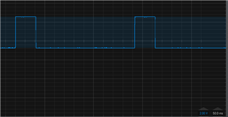
I have another question. I just tested my circuit with external boot diode. PWM signal: Ton = 20ms; Toff = 100 ms, but at the output I get 0.4 V. I added 4.7 uf capacitor as you suggested.
With the boot cap increased to 4.7uF, to ensure that VDD voltage does not drop too much during the initial boot cap charging, I think you need to increase the VDD cap. Sorry I did not mention that before. We usually recommend a 10x HB cap value for the VDD cap to avoid excessive drop on VDD. Is it possible to try that. Also did the circuit work OK with the lower boot cap value of 1uf as shown in the schematic?
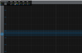
If you are still having issues, can you send plots of VDD, BOOT, PHASE and Ugate, Also a plot of PWM, Phase, Lgate and Ugate. We need to see if the boot voltage is OK during the turn on time.