This thread has been locked.

If you have a related question, please click the "Ask a related question" button in the top right corner. The newly created question will be automatically linked to this question.

TPS54260: TPS54260 overcurrent protect when Inverting Power application

Part Number: TPS54260

Tool/software:

Dear sir,

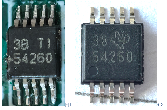
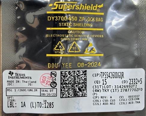
Recently Delta reported that  some TPS54260DGQR (the left) can work well,  but some IC not (the right) which is from TI sample stock,  Label as following.

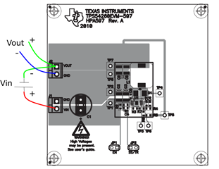
Delta's schematic as following:

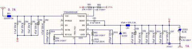
Inverting application:   Input:  22V~ 26V,   output: -15V/ 1A,  more information in the attached EXCEL.

Copy of TPS54260相关参数.xlsx

The issue description:  when power up of +24V input,   IC will be into overcurrent fault at once.  

Can you comment on the debug tips?

Regards,

Jack

  • Hello Jack

    I would need your help to understand the issue clearly. 

    --when power up of +24V input, IC will be into overcurrent fault at once.

    Does it mean device went into current limit momentarily and came out of it?

    Is there any load on at output other than LED during startup?

    Could please share the waveform indicating the issue?

    Thank you

    Regards

    Onkar

  • Hi Onkar,

    Delta used this device for several years, only reported this issue recently. and there is no new PCN after my check.

    Based on Delta R&D feedback that there is no PWM output when power up ( Vinput = +24V.), and customer test it with no load, it is same.

    Can you support the following questions firstly:

    Q1:  Help check the parameter in Delta's schematic is reasonable based on their application (In Excel document.)

    Q2:  What's the difference the following two top mark IC?

    Regards,

    Jack

  • Hello Jack 

    I have one comment their schematic. compensation components need improvement. Rcomp(RR3) value is bit small and Chf(CR13) looks pretty big. They can use values suggested by the quickstart calculator. Rest of the schematic looks fine to me.

    Two ICs shown in picture are sourced from different assembly sites but functionally, both are same. To get more information about the ICs, could you please share the lot no. or label for the left one.

    Thank you 

    Regards

    Onkar

  • Hi Onkar,

    Delta changed RR3/ CR13 based on the values from our calculator tool, but this problem can't be fixed.

    Do you have a TPS54260 Inverting power EVM to repeat this issue?

    And I plan to on-site check this issue next week, do you have some debug tips for me?

    Regards,

    Jack

  • Hello Jack

    TPS54260 EVM (TPS54260EVM-597) can configured in the following way to make it inverting buck boost.


     I'll provide you my suggestions for testing on Monday. As I am out the office today.

    Sorry for the inconvenience

    Regards

    Onkar  

  • Hello Jack

    Try probing following nodes to understand the issue.

    1. SW node w.r.t Vout
    2. Voltage across CR2
    3. SS pin voltage w.r.t Vout
    4. Inductor current
    5. GA w.r.t Vout

    Thank you

    Regards

    Onkar

  • Hello Jack

    Let me know when are going to conduct experiment. If possible, we can connect online over webex while you are testing.

    Thank you 

    Regards

    Onkar

  • Hello Jack 

    Any update on this?

    Thank you

    Regards

    Onkar Bhakare

  • I am closing the thread due to inactivity. Feel free to reopen it at any time.

    Thank you

    Regards

    Onkar