This thread has been locked.

If you have a related question, please click the "Ask a related question" button in the top right corner. The newly created question will be automatically linked to this question.

TPS4811-Q1: Random, short MOSFETs interrupts using TPS48110 driver

Part Number: TPS4811-Q1

Tool/software:

Hi,

We are using the TPS48110 high side switch for driving 2 parallel NTBLS0D8N08XTXG MOSFETs. Please, find attached schematics below:


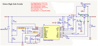
Then, we replace R8 and C16 for managing inrush current in our load: CLOAD = 1500uF, I startup = 80 mA @ 5V. After startup, our load can demand up to 250A peaks. We used your SOA calculator Excel sheet for calculating these values and we have tried 2 different configs: R8 = 470 kOhms, C16 = 220 nF, C18 = 4.7 uF and R8 = 100 kOhms, C16 = 440 nF, C18 = 4.7 uF. 

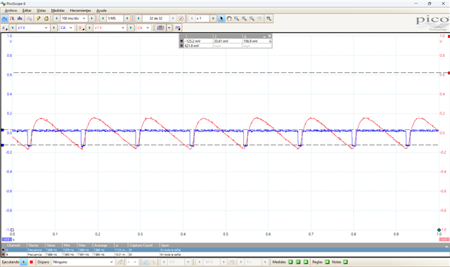
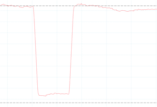
With any of these configs, we get VMOTOR drops when Iout is 35A or higher. Below you can see Vs and Vgate traces in AC coupling. As you can see, Vs (blue trace) perfectly follows Vgate (red trace):


After some time and by increasing the load, MOSFETs get shortcircuited (all their pins), probably due to these instant interruptions at high load. I have also checked FLT_I signal and it doesn't show any error. It doesn't follow neither Vs nor Vgate.

My question is: What could cause these voltage drops at Vgate at high loads?.

Kind regards.

My question is: what could cause this voltage drops at Vgate? 

  • Hello, 

    It looks to me like the capacitance is too much for your parameters. Have your probed the bootstrap capacitor to make sure it is fully charged? You can also consider using the pre charge path to make sure that the output load is fully charged before you turn on the main gate. 

    Have you used the device design calculator? There is a specific section that calculates the R1, R2, C1 and CBST values for targeted INRUSH and start up time. 

    https://www.ti.com/tool/download/TPS1211-Q1-CALC

    Thank you, 

    Sarah

  • Hi Sarah,

    -> I checked bootstrap voltage at low load (around 1A) and it was charged at 11,36V. If bootstrap cap charge would be a problem, why these GATE drops just appear when load begins to grow (from 30A or higher)?. How is bootstrap voltage and load current related?

    ->Pre-charge path isn't an option for this PCB iteration.

    ->Effectively, I have used your calculation sheet for this IC. Additionally, I used your SOA calculator sheet too. components have been placed following these both tools.

    Many thanks and Merry Christmas!

  • Hi Roberto, 

    I The bootstrap capacitor will just ensure that the FETs are able to turn on correctly. You should verify that this is also the correct voltage at the higher 30A load value. 

    Can you explain how you are applying the load? What is the load? Are you starting at 1A and then increasing to 30A? 

    What you are describing is really a classic case of capacitive load driving where the FETs either are not designed to handle the expected load conditions or are handling too much INRUSH current. (Slew rate control design).

    Thank you, 

    Sarah

  • Hi Sarah,

    -> Again, I don't understand why the bootstrap voltage should change with respect to the load. If the MOSFET is able to turn ON at low load and the bootstrap voltage is fine, why should it decrease when load increases? 

    -> Our load is an ESC and a BLDC motor which can consume up to 200A peak. At startup, the load initialized with a peak current consumption about 80 mA (we have measured it). Then, we progressively increase the motor speed, so the current consumption increase. This interruptions don't appear up to reaching a load current around 30A.

    ->Effectively, the ESC has a great capacitive input component, but we have calculate inrush current control components following your calculations sheets and it works. The problem is not at startup. We have tried 50 ON/OFF cycles with the ESC and the motor connector and we haven't suffered any issue. The problem appears at steady state, once nominal load current is 30A or higher. Finally, the MOSFET breaks down due to this short interruptions at such big load current.

    Thank you for your support.


  • Hi Roberto, 

    I'm not saying the bootstrap voltage should change with respect to the load. I just want to make sure the operation is typical since we are seeing the gate voltage drop. 

    What supply are you using? The first graph you showed indicates the supply is dipping. Since this is only happening at higher current values I wonder if your supply is reaching a limit. If you are using a bench top supply you can parallel these to support higher current draw. 

    Thanks,

    Sarah

  • Hi Sarah,

    Our supply are 2x 6S LiPo batteries, serial placed (12S). Each one has 6,8Ah capacity and 120C discharge rate, so most probably the power source is not the root cause.

    Let's suppose that the bootstrap voltage isn't kept from 30A load or higher. Which would be the solution?

    Thanks,

    Roberto.

  • Roberto, 

    If your CBST is not charging correctly at 30A then you are not using an adequate value. Typically you can start with equation 18 in the datasheet, but you should also use equation 4 to make sure you are accounting for the additional load from slew rate controls. Your below comment worries me as your CBST value remains 470nF despite changing C16. Have you accounted for this? Please verify that the bootstrap voltage is reaching full capacity like at lower current and verify the gate voltage. 

    we have tried 2 different configs: R8 = 470 kOhms, C16 = 220 nF, C18 = 4.7 uF and R8 = 100 kOhms, C16 = 440 nF, C18 = 4.7 uF. 

    Thanks,

    Sarah

  • Hi Sarah,

    If you check again my comments that you were about, you will see that in both tests, CBST was 4.7 uF (C18), it didn't remain to 470 nF. Anyway, I have checked equations that you mentioned one more time and I have gotten the expected results:

    -> For C1 = 220nF, CBST > 2.5 uF (from equation 4). We are placing a CBST (C18) = 4.7 uF, 25V rated, almost twice what equation 4 returns.
    -> For C1 = 440nF, CBST > 4.78uF (from equation 4). We keep C18 = 4.7.uF, so, for this C1 value, your hypothesis could be right.

    But, the voltage drops from 35A load or higher appeared for both tests. And, again, our load initializes with a maximum current consumption of 80 mA. From here, the MOSFET should be always ON, this is, CBST should remain fully charged. It doesn't need to be charged again. Of course, due to this unexpected drops on VGATE, the MOSFET needs to be turned ON at 35A load, which clearly damage it after some of this drops.

    Just to clarify, these were our tests:

    -> To tie EN_MOTOR high. MOSFET is perfectly enabled. Max current consumption at start up = 80 mA. 50 cycles tried.
    -> EN_MOTOR is high for the rest of the test.
    -> To speed up motor progressively. Current consumption goes from 1A to 35A in a very smooth way. No voltage drops neither at VS of VGATE appear.
    -> Still increasing motor speed. Current consumption goes from 35A to 70A in a very smooth way. Unexpected, unwanted voltage drops at VS and VGATE appears in this whole range. The higher consumption, the higher voltage drops frequency.

    -> Finally, MOSFETs break down due to heavy inrush current, as they need to recover from these voltage drops at a 35A load (or higher).

    I hope this comment helps.

    Roberto. 

  • Hi Roberto, 

    I understand. Let me check on this. 

    To add to the debug have you tried starting up at the higher current load? Just to verify the ramp has nothing to do with it and the Supply and FET can handle higher load current. 

    Thanks 

    Sarah

  • Hi Sarah, 

    Our MOSFET's SOA is not a great one, so any start-up current higher than 2A (for the current inrush current control set) will break down the MOSFET. I tried with other load currents within this range and the ramp was the same all the time.

    Which specific aspect from the ramp up would you like to check?

    Roberto

  • Hi Roberto, 

    I understand, it doesn't sound like the system may be fully optimized for your higher currents. I would ask you to please test out your load condition on our EVM. These FETs will be able to handle the high current you are expecting. From there if you still have issues we can revisit the topic. Please keep me updated if you still run into issues using the EVM. 

    Thank you,

    Sarah

  • Hi Sarah,

    While we get your EVM, I still making measures. I have caught that, even when the HS is OFF, there are some 200 mV voltage drops at Vs pin, at a very stable frequency of 5 Hz. Please, take a look at the image below:


    These drops are the same with the HS turned ON. Could the input Vs filter be limiting input current too much?. Could this noise be the reason of voltage drops at MOSFET source at higher current?

    Kind regards,

    Roberto.

  • Hi again Sarah,

    First of all, I don't know why the issue is marked as solved when it isn't.

    Now, I figured out that these drops at Vs happen when charge pump is turned ON and VBST (red trace) starts to grow up, as shows the image below:


    Then, I have been testing a new input filter set up: R54 = 10 Ohms, C62 = 2*1uF + 100 nF. Amplitude of that drops at Vs voltage has been reduced from 200 mV to 18 mV, but Vgate drops still present.

    In the image below you can see as Vgate (red) goes down because, for some reason, V BST (blue) goes down. It is like charge pump is suddenly disabled:


    Then, when MOSFET is fully OFF, charge pump is turned ON again.

    Increasing C BST doesn't make any effect.

    Could adding an auxiliar power supply to BST solve this problem?

    Kind regards,

    Roberto


  • Hi Roberto, 

    "Green resolved" indicates the customer resolved the ticket. It is only yellow if customer doesn't confirm resolved. 

    The V_BST-SRC should saw tooth with a delta of about 2V only as the charge pump will regulate this around 12V. (See below graph) 

    The EN/UVLO should remain stable during this time. Can you please confirm the UVLO is not being violated? this could cause the charge pump to shut down due to the FLT. 

    Adding the auxiliary supply could be a good debug step. This will help if you need more than 100uA coming from the charge pump. But I would first confirm the UVLO is not being violated. 

    Are you still planning to test with the EVM? 

    Thank you, 

    Sarah

  • Hi Sarah,

    Yesterday I checked the PCB with the auxiliar supply for bootstrap cap and the problem stills present. Moreover, I checked the signals that you mentioned, and I could just see some small voltage dropouts in EN/UVLO (red trace). They don't reach UVLO threshold:


    As you can see in the second image (EN/UVLO detailed drop), it doesn't seem like a sampling issue, the oscilloscope seems to have gotten many samples at the low signal level.

    EVM test sill planed, but we still waiting for receiving it. Anyway, I have compared both schematics (EVM and mine ones) and I can't see any significative difference, just the MOSFET. But we can't use the same MOSFET than you, as we need to be able of carrying up to 200 A continuous current.

    Kind regards,

    Roberto.

  • Roberto, 

    I understand that the EVM design might not be sufficient for your total system needs. My intention is to focus on the failure (loads exceeding 35A right?).

    I dont think its valid to design the system only keeping in mind the ramp up. If your FETs dont work at higher loads this would be dangerous.  

    Earlier you stated you could not verify 35A worked (at start up, not ramp) because of your FET selection, but the ones on the EVM will work for this. This will help identify if the issue persists if the device is having an issue or if its just the system its in. Then we can try to design better for Vin, FET, and Vout requirements. 

    Thank you, 

    Sarah