This thread has been locked.

If you have a related question, please click the "Ask a related question" button in the top right corner. The newly created question will be automatically linked to this question.

UCC28180: UCC28180

Other Parts Discussed in Thread: TIDA-00443

Tool/software:

Hi guys, 

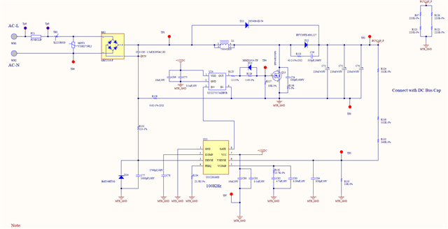
I used UCC28180D and gate driver UCC27517ADBVR to design a PFC and output is 390V following the design reference 900W TIDA-00443 for our 230V motor drive project. The load is BLDC pump, max power is around 650W. The output voltage is around 393V. After running the pump for about 10 minutes, the current resistor 20m ohm burnout. check the Mosfet is bad( D, G, and S all short together). The fuse and bridge are both good. The gate driver is bad( the 15V and GND short together). What i believed is that the mosfet is short and the current is too large and burned out the current sensing resistor and some of the trace. The question is what caused the gate driver short the VCC and GND? please provide some help.

  • Huangsong,

    There could be many reasons. Have you select the right FET to begin with? Is there a heatsink on the FET? 

    Can you replace the bad units and monitor the waveform to see what can happen?

  • Hello Huangsong, 

    Most likely, the gate-driver IC failed as a consequence of the MOSFET failing. 
    Often when a MOSFET fails the gate-drain insulation fails and high drain voltage appears at the MOSFET gate pin.  This high voltage is then applied to the gate-driver output and the driver cannot withstand it.  Then the driver fails, too, in your case shorting VCC to GND.  Often, the driver failure also allows high voltage to the output of the UC28180 control IC, and causes that to fail, too. 

    The real question is: What caused the MOSFET to fail? 

    I assume that the current-sense resistor can withstand the steady-state power loss at full power, so it did not burn out by itself first, but only by excess current from the MOSFET failure.

    MOSFET failure can be due to excess voltage stress, excess current stress, or excess temperature rise. 
    Excess voltage usually causes failures quickly, not after some time, so this probability is low.
    Excess current stress can happen if the inductor saturate due to excess temperature rise of the inductor.  Please check that.
    Excess junction temperature of the MOSFET can happen due to excess current, or unexpected switching loss, or insufficient heatsinking of the normal power loss.
    Please check each of these.

    Regards,
    Ulrich 

  • Hi Ulrich, 

    thanks for your prompt reply. There is a big aluminum casting on the back and the MOSFET is attaching to this aluminum casting with a thermal pad. There is also a fan powered by the motor and blows the air to the aluminum casting. I will focus on the heat performance of the MOSFET. Below is the the schematic, please help check. thanks The load is BLDC.

  • Hi Huangsong, 

    Thanks for the schematic diagram. 

    Also check into the output diode D22 temperature rise and reverse recovery current.

    Although it is an ultrafast part, it may be getting too hot and increasing Irr more than the MOSFET can handle.   
    at 100kHz frequency, consider using a SiC diode in this position. 

    Aside from that check to see if gate-drive diode D23 can handle the peak turn-off current going through it.  
    Although if it fails short or open, I don't see how it could cause the MOSFET to fail. 
    (Note: precision resistors are not really needed at R125, R126 and R127.)

    Regards,
    Ulrich

  • Hi Ulrich,

    Thanks for your comment. Can I send email to your work email by my work email address? This can be better communication.

    Thanks

  • Hi Huangsong, 

    At this time, I'd prefer to remain within the E2E Forum so that others can learn from this. 
    So far nothing really proprietary is being discussed. 

    I am going off work for the weekend now, so replies to new posts may not happen until Monday.

    Regards,
    Ulrich