This thread has been locked.

If you have a related question, please click the "Ask a related question" button in the top right corner. The newly created question will be automatically linked to this question.

BQ27Z561-R2: Occasional SDA bit does not become 0V and communication at some point fails.

Part Number: BQ27Z561-R2

Tool/software:

Dear TI community,

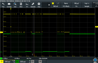
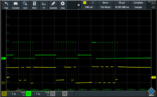
We are working on BQ27Z561-R2 battery pack project. Battery pack with gauge inside and that solution is connected in to the system. After testing prototype in greater quantities we noticed that after some random time communication with gauge fails.  We are now in the process of hunting down the problem. After probing I2C line we noticed strange behavior.  When communicating with other system I2C devices that phenomenon is not present and I2C waveform looks normal. STM32 communication with BQ27Z561-R2 gauge looks like shown in screen grab below. 

SDA line sometimes does not reach 0V

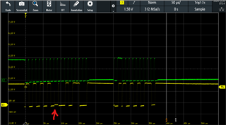
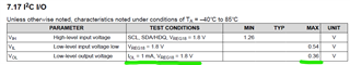
 Tried to use I2C line buffer FXMA2102 but that just amplifies the problem and communication failure occurs more often. Screen with FXMA2102 used, signal on the gauge side of the buffer:

So we have tried two different scenarios:

1. When I2C buffer is not used, battery pack gauge always see I2C line and its pull-up voltage. Standard I2C situation.   

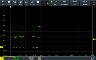
2. When I2C buffer is introduced we gain additional feature to disable I2C line going to the battery pack and we use that. After gauge read out we disable buffer. SDA and SCL both become low. We then activate I2C line every ~5sec to  update status from battery . I'm not sure if that is important so I decided to mention.

In both scenarios outcome is the same. Communication with gouge fails after some random time and we are not able to read the status. We persistently try to read the status few times. Its not only one failed communication attempt. 

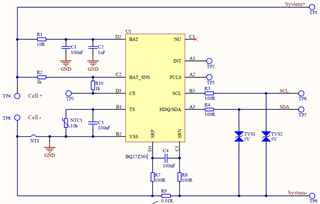
Pack side gauge schematic is very basic and mimics the evaluation board

Regarding the related question I tagged to my question - we have checked and seems our STM32 uses Open Drain topology so its not the case as in nRF5340 that related question was referring to.  Hope you will have some hints on what to do or check next. 

Wish you happy upcoming holidays!

Best regards, Aivaras

  • Hello Aivaras, 

    How are the I2C lines being pulled up? 

    Are you able to isolate the BQ27z561-R2 and the STM32 on the comms lines to see if this behavior persists? I am wondering if another downstream device could be causing a conflict on the bus. 

    Additionally, please ensure that the STM32 supports I2C clock stretching. 

    Regards, 

    Robert. 

  • Hello, thanks for your replay and support effort. 

    I tried 2 different HW variants. With I2C buffer and without. For simplicity lets continue with HW variant without I2C buffer where all I2S devices are connected directly to STM32 - battery gauge, EEPROM, Accelerometer, RTC... Communication lines are pulled up by 4,7kR resistors to main Vcc rail 1.8V. Clock stretching is enabled. 

    Communication to other devices looks normal, communication to battery gauge has those raised logic low levels. Looking in to communication structure I see that SDA 9 bit , CLK stretch period are raised. Also SDA last word (after second stretch period) is raised from start to finish. Is this a sign that battery gauge is not able to sink the commination lines ?   I was not able to find recommendations for pull up resistors in the documentation. Maybe you can suggest?  

    I replaced 100R series resistors which were suggested in gauge reference design for EMI protection. Replaced with 0R ant that helped slightly, the intermediate low level is now closer to zero. 


    Regards

    Aivaras

  • Hello, 

    Our EVMs use a 10k ohm pull up to a steady 3.3V supply. Are you able to isolate the gauge and communicate with it? 

    Regards, 

    Robert. 

  • I can only desolder all other I2C devices and request for a custom FW, I have no other means to isolate gauge.

    I tried replacing pull up resistors to 10kR and the intermediate logic Low level become even smaller, almost negligible. For me this only adds to assumption that problem is in BQ27Z561-R2 that it has very limited pull down capabilities and can sink not enough current. Maybe this is particulary true with 1,8V mommunication voltage. 

    In documentation there is almost no info about communication lines current sink capabilities or pull up resistor values. The only info I found is this

    Does this mean that the maximum sink current is 1mA ? 

  • Hello, 

    The 1mA is the sink current for this particular spec. 

    Regards, 

    Robert. 

  • Used a I2C decoder to get better understanding what's going on. All intermediate logic low levels are associated with gauge sending info to master. Acknowledge/data/CLK stretch. This cements the idea that  BQ27Z561-R2 has limited sink current and users must use 10kR pull up resistors, especially with 1,8V voltage. Worst case 4.7kR. Sad that this info is not in Datasheet or Reference Manual.