Tool/software:
Hi
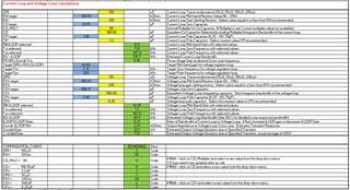
Can you help review my customer's excel calculator file and schematics attached below ?
we would like to check if any where we can improve the phase marging and gain margin, and also improve the output ripple. thanks !
Tool/software:
Hi
Can you help review my customer's excel calculator file and schematics attached below ?
we would like to check if any where we can improve the phase marging and gain margin, and also improve the output ripple. thanks !