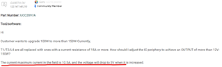
This thread has been locked.

If you have a related question, please click the "Ask a related question" button in the top right corner. The newly created question will be automatically linked to this question.

UCC2897A: spec check

Part Number: UCC2897A

Tool/software:

Hi 

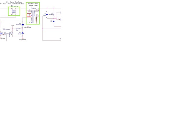
Customer wants to upgrade 100W to more than 150W Currently,

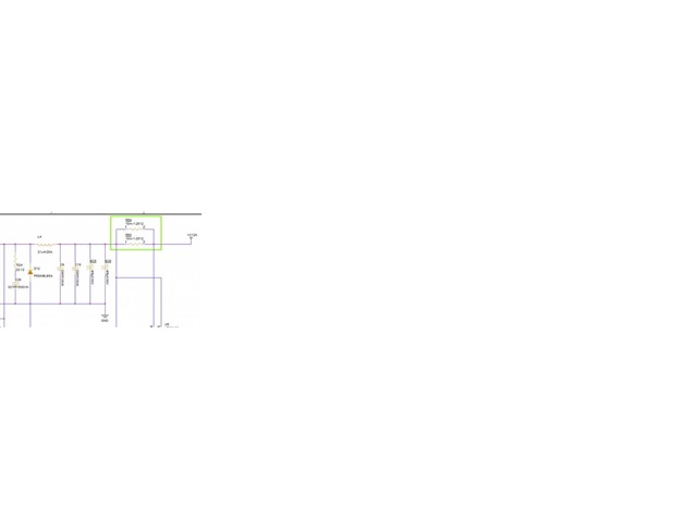
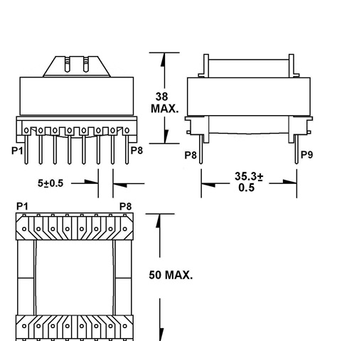
T1/T2/L4 are all replaced with ones with a current resistance of 15A or more. How should I adjust the IC periphery to achieve an OUTPUT of more than 12V-150W?

The current maximum current in the field is 10.5A, and the voltage will drop to 5V when it is increased.

5756.ucc2897.pdf

  • Hi,

    What is the primary side OUT pin duty cycle at 10.5A load current?

    What is the OUT pin duty cycle when Vout is 12V, and how high the current can be carried when Vout keeps 12V? 

    What is input voltage at above test?

    What is T2 turns ratios specification?

  • Hi Hong Huang

    1. 12Vin, primary duty cycle: 42%,secondary duty cycle: 58%
    2. 36Vin: ,primary duty cycle: 81%,secondary duty cycle: 15%
  • Hi,

    Please answer each question with question number so I can understand which answer is for which question.

    1. What is the primary side OUT pin duty cycle at 10.5A load current and at what input voltage?

    2. What is the OUT-pin duty cycle when Vout is 12V, and how high the current can be carried when Vout keeps 12V, at what input voltage? 

    3. What is T2 turns ratios specification?

  • Hi Hong Huang

    Attached is the updated schematic (corrected T2)

    1. What is the primary side OUT pin duty cycle at 10.5A load current and at what input voltage?

    ------- primary duty cycle: 42%, input voltage: 12V

    2. What is the OUT-pin duty cycle when Vout is 12V, and how high the current can be carried when Vout keeps 12V, at what input voltage?

    ------- Not sure which pin the OUT-pin refers to, I measured PIN4,5 & PIN14,15 This experiment input voltage: 12V, T2 I(RATED) max 15A, Load: 15A, Vout can Keeps at 12V PIN4,5 - duty cycle: 31% PIN14,15 - duty cycle: 58%

    3. What is T2 turns ratios specification? -

    ------ Turn Ratio: 3:7:7

    Also, I would like to ask the first question, is the primary side OUT number PIN 4 and 5 correct?

     UCC2897 Schematic.pdf

  • Hi,

    1. What is the primary side OUT pin duty cycle at 10.5A load current and at what input voltage?

    ------- primary duty cycle: 42%, input voltage: 12V

    At this condition, when you increase the load current to be larger than 10.5A, say 15 A, what is the duty cycle measured on U2 pin 15 (OUT pin)?

    2.

    U2 pin 15 is OUT pin

    So at 12V input, when the load current = 15A, U2 pin 15 (OUT pin) duty cycle = 58%, right? What is the output voltage Vout, is it still 12V?

  • Hi Hong Huang

    1. What is the primary side OUT pin duty cycle at 10.5A load current and at what input voltage?


    ------- primary duty cycle: 42%, input voltage: 12V


    At this condition, when you increase the load current to be larger than 10.5A, say 15 A, what is the duty cycle measured on U2 pin 15 (OUT pin)?

    ------- Load 15A,U2 PIN15 duty cycle = 65%


           2.U2 pin 15 is OUT pin


    So at 12V input, when the load current = 15A, U2 pin 15 (OUT pin) duty cycle = 58%, right? --- No,58% is T2 PIN14,15

    What is the output voltage Vout, is it still 12V?

    ------- 12V input,Load 15A,U2 PIN15 duty cycle = 65%.

              Yes, Vout is still 12V.

  • Hi,

    Back to your original question red underlined, what was the condition, input voltage, output voltage and output current, it sounds not consistent to your latest reply.

  • Hi Hong Huang

    R63 & R64 are originally 20m, with a maximum current of 10.5A After changing to 10m, the current can be 15A

  • Hi,

    It sounds like no problem to you now. 

  • Hi Hong Huang

    If you want to output 24V/8.5A

    1. Can we calculate the number of turns and inductance of each transformer according to the attached transformer dimensions, and then ask the manufacturer to wind the sample according to this value?

    2. In addition to replacing the transformer, what other parts values ​​need to be changed?

  • Hi,

    You need to talk to your transformer vendor or builder to find out. Usually, the transformer number of turns also need to consider the core material (for example Bmax, etc) and other things, so your transformer builder would need to know if the number of turns are good, and also if the bobbin and the core you selected are ok to fit in that many of turns with sufficient wire gage. So not a simple process.

    On the UCC2897A converter that needs to consider if ok or to change, please follow this below application note to check based on your converter specifications.

     Understanding and Designing an Active Clamp Current Mode Controlled Converter (Rev. A)