This thread has been locked.

If you have a related question, please click the "Ask a related question" button in the top right corner. The newly created question will be automatically linked to this question.

LM25184-Q1:当驱动SIC是,输出电压被拉低

Part Number: LM25184-Q1
Other Parts Discussed in Thread: LM25184

Tool/software:

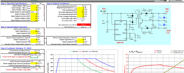
下面是电路的原理图和计算器的理论值,在空载条件下,+18V 电压将被拉低,导致输出关断。我将220uF 电解电容器与 18V 输出电压并联,电压稳定下来。当我连接负载时,输出电压再次不稳定。我测量了 FB 电阻器上的电压,没有严重的干扰。

  • Hi Yu,

    Reviewing your Calculator Design tool, the output power is limited at ~9.5W at Vin_min. However, your power requirements are ~11.25W (9W+2.25W). What is the load condition when Vout is pulled low? I suspect the converter is going through an overload condition and then controller will pull out Vout and enter in hiccup mode (see below). 

    I recommend the following:

    -Does Vout is pulled low at lower loads? At what load Vout is pulled low?

    -To overcome this, it is recommended to increase turns ratio Nps.

    -Also, please share the waveforms labels in  English, I don't speak Chinese.

    Thank you

  • Hi Junxiong,

    Thank you for designing with the LM25184.  Firstly, your output capacitor may be insufficient.  Note that the calculator suggests a min capacitance and it is the effective capacitance.  Your 10uF is just a surface value, and under dc voltage bias its effective capacitance would reduce.  Please check with the capacitor vendor to find the worst case capacitance under the output voltage, then make Cout adequate for both outputs. 

    Secondly, your output Zener voltage rating does not seem be to correct.  For the 18V output, the Vout setting voltage is 18V nominal, then you should choose a Zener of 19 to 20V for D3, and 5.09 to 5.6V Zener for D5, to prevent them from permanent conducting.  Basically, the Zener there is to limit Vout under no load conditions, and they should be at least 5% higher than the Vout setting voltage.    

    Thirdly, did you install the dummy load resistor as shown on your schematic?  If they are used properly, you may save the Zener. 

    Please also capture the SW voltage, zoomed in to show a complete switching cycle, at the moment the switching stops and re-starts, namely the two edges below.  Please also show VIN and EN/UVLO signals in the same scope pictures. Use the a probe with short ground lead for SW.   When you share your scope pictures, please label the traces, and also tell the operating conditions like the input voltage, load current, etc.

    Best Regards,

    Youhao