
- Ask a related questionWhat is a related question?A related question is a question created from another question. When the related question is created, it will be automatically linked to the original question.
Tool/software:
Hi team,
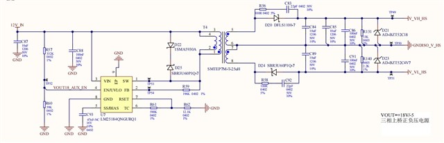
Could you please help review below schematic and give some suggestions? Thanks!
7115.LM(2)518x PSR flyback converter quickstart tool revB.xlsx
Regards,
Ivy


