Other Parts Discussed in Thread: TPS3760,
Tool/software:
Hello Team,
We are using part->LM5150QRUMRQ1 in our design.
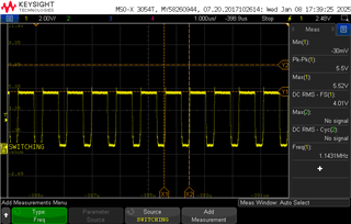
When the load is not connected at Output of Boost Converter. The boost operation is happening, But as soon as we connect the load-0.150A, the boost operation is not happening
After application of load current, AVCC voltage is also decaying and is not fixed at 5V.
Can you please support on debugging this issue?
Attached are schematics of this IC and other waveform captures
Regards
Sumit
LM5150Q_Boost_Schematics.pdf
Boost Output Without Load
Boost Output with Load
AVCC Without Load
AVCC With load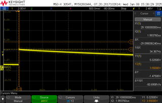
Boost Switching