- Ask a related questionWhat is a related question?A related question is a question created from another question. When the related question is created, it will be automatically linked to the original question.
Tool/software:
Greetings, professionals and forum visitors. I would like to ask your help with LM5145 converter. In my project, converter being powered by 48V Li-Ion battery (input voltage range 41-55V), and should step it down to 24V with top current of 6A. With no or light load everything works just fine, but after 4A it shuts down, or outputs only half of the required voltage (you may see on video). Increasing Rilim or changing LM5145 itself made no results, also there is no overheating in converter chip, mosfets or inductor. I'll attach plots from HO, LO and SW down below, as well as schematics and PCB. Where should I suppose to look to find a problem? Thank you in advance.
Load test #1 (Input 56V):
Load test #2 (48V input):
HO with no load:

LO with no load:

SW with no load:

Signal width on SW under load of 3A starts chaotically change, not sure is it ok or not (as well as signals on LO and HO, acts the same):
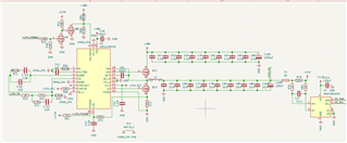
Schematics:
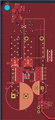
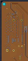
PCB top layer:
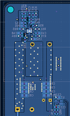
PCB inner 1 layer:
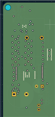
PCB inner 2 layer:
PCB bottom layer:
LM5145 Quick start calculator with actual values